Table of Contents
Advertisement
Quick Links
2561898G
REV. G 1006
Printed in U.S.A.
SAFETY MESSAGE TO INSTALLERS AND USERS
People's lives depend on your safe installation
of our products. It is important to read, under-
stand and follow all instructions shipped with
the products. In addition, listed below are some
other important safety instructions and precau-
tions you should follow:
•
To properly install lightbar, you must have
a good understanding of automotive sys-
tems, along with proficiency in the installa-
tion and use of safety warning equipment.
•
DO NOT install equipment or route wiring
in the deployment path of an air bag.
•
This product contains high intensity LED
devices. To prevent permanent eye damage,
DO NOT stare into the light beam at close
range.
•
A light system is a high current device. In
order for it to function properly, a separate
ground connection must be made. If practi-
cal, it should be connected to the negative
battery terminal. At a minimum, it may be
attached to a solid metal body or chassis
part that will provide an effective ground
path as long as the light system is used.
•
When drilling into a vehicle structure, be
sure that both sides of the surface are clear
of anything that could be damaged.
•
Locate the light system controls so the
VEHICLE and CONTROLS can be operated
safely under all driving conditions.
•
The mounting system should be periodi-
cally inspected to ensure that it is securely
attached to the vehicle.
•
File these instructions in a safe place and
refer to them when maintaining and/or
reinstalling the product.
Failure to follow all safety precautions and instruc-
tions may result in property damage, serious injury, or
death to you or others.
I.
GENERAL.
HEAVY OBJECT
Get assistance when lifting or installing.
Failure to do so will cause permanent bodily
injury.
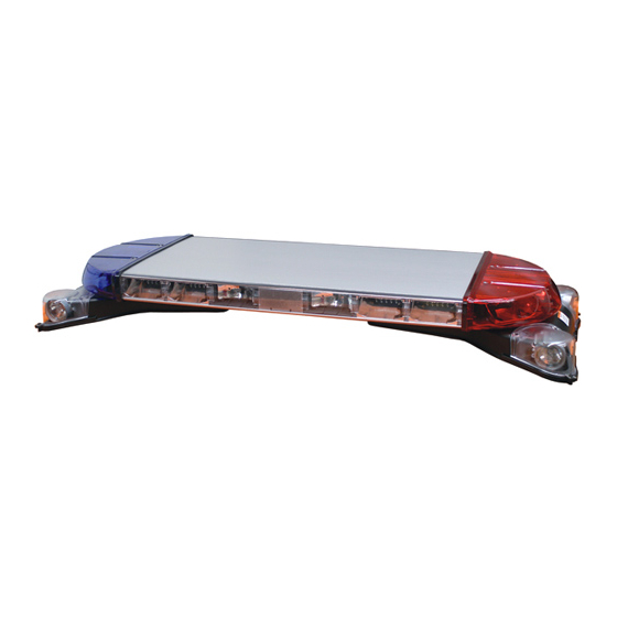
Installation AND MAINTENANCE INSTRUCTIONS FOR
RAYDIAN® LED LIGHTBAR
The Raydian is a LED light bar, with supplemental white
halogen area lighting, designed for use with Federal Signal
lightbar controllers and/or single switches rated at 2-amperes
and above. The base is a two piece extruded aluminum profile
with polycarbonate lenses and end domes. The unit is supplied
with mounting hardware and an eighteen-foot cable and has
an operating temperature of -40°C to +65°C.
II.
UNPACKING.
After unpacking the Raydian light assembly, inspect it for
damage that may have occurred in transit. If the unit has been
damaged, do not attempt to install or operate it. File a claim
immediately with the carrier, stating the extent of damage.
Carefully check all envelopes, shipping labels, and tags before
removing or destroying them.
III.
INSTALLATION.
A.
General.
Before proceeding, ensure that the lightbar has been
installed on the vehicle roof in accordance with the instruc-
tions packed with the mounting kit. The lightbar is completely
wired at the factory and does not require any additional inter-
nal wiring. All the conductors necessary for control of any and
all basic and optional functions are contained in the cable. The
basic light functions of the unit must be controlled by a user-
supplied control head.
Light system controls must be located so that
the VEHICLE and CONTROLS can be operated
safely under all driving conditions.
1.
Route the control cable into the vehicle and near
the eventual location of the user-supplied control head. Route
the Power cable into the vehicle and to the battery.
2.
For proper light operation, the control cable must
be properly terminated inside the user-supplied control head.
Using figure 1 and table 1 as a guide, make the appropriate
electrical connections. Ensure that the lines are adequately
fused as shown and that the switch capacity is adequate for
the current requirement.
Reverse polarity may damage any power supply and
prevent operation. Ensure that the correct polarity is
observed. The positive (+) power lead must be fused at
the source for 40 amps.
3.
Connect the separate 10 gauge black lead to the
vehicle battery ground terminal (-) and the separate 10 gauge
red lead to the vehicle battery hot terminal (+).
All the lightbar functions can be activated by applying
12VDC to the appropriate control line. The 10 gauge
black and red power leads must be connected to their
respective battery terminals for a function check.
NOTE
Advertisement
Table of Contents

Related Manuals for Federal Signal Corporation RAYDIAN


Summary of Contents for Federal Signal Corporation RAYDIAN
- Page 1 INSTALLATION AND MAINTENANCE INSTRUCTIONS FOR RAYDIAN® LED LIGHTBAR SAFETY MESSAGE TO INSTALLERS AND USERS The Raydian is a LED light bar, with supplemental white halogen area lighting, designed for use with Federal Signal lightbar controllers and/or single switches rated at 2-amperes and above.
- Page 2 WARN 1 WHT/BLU WARN 2 WARN 3 WHT/GRN WARN 4 WHT/GRY SPEED * 42” Raydian with 7-head SignalMaster - Use SS2000SM set to 6-head, 330132, or 331112. 54” Raydian with 8-head SignalMaster - Use SS2000SM set to 8-head, 330102, or 331102.
- Page 3 Steady Burn Red. RELAY When the Raydian is equipped with a Steady STROBE SUPPLY Burn Red led module, applying 12VDC to the Orange wire will +12V CONTROL LEAD cause that module to operate when any mode input is selected. (12V SIGNAL ACTIVATED) Intersection Mode.
- Page 4 • Apply 12 VDC to the 10GA RED power • To change the configuration, momentarily lead. One half of the front of the lightbar will light steady to apply 12 VDC to the Steady Red (ORG) control input wire. The indicate which configuration is selected (driver side - 12 VDC configuration will switch to the opposite mode, and the alter- activate / passenger side 12 VDC deactivate).
- Page 5 MAINTENANCE. Crazing (cracking) of lenses will cause reduced effectiveness of the light. Do not use cleaning agent (which will cause crazing) such as strong detergents, solvents, or petroleum products. If crazing of lenses does occur, reliability of 290A4747 light for emergency signaling purposes may be reduced until lenses are replaced.
- Page 6 1/4” drift punch (or the 1/4” shank of a #2 Phillips screwdriver) is used to align the holes in the dome, top plate, end bracket, and bottom plate. While keeping slight pressure inward on the dome, align both holes, leaving the drift in the second hole while starting the screw in the first hole.
- Page 7 BACKPLANE REFLECTOR ASSEMBLY PC BOARD ASSEMBLY PCB ASSEMBLY RIVSCREWS LOCKING TAB #6 PHILLIPS SCREW LED MODULE FRESNEL LENS 290A4750 Figure 10. Assembly is the reverse of disassembly. Prior to installation of the PCB assembly, ensure that the LED connec- tor pins on the PCB are not bent or damaged. BASEPLATE 290A5055 H.
- Page 8 1/4" FLAT WASHER LED, 3 Button, White (3 req’d.) 8625106-W 1/4" LOCKWASHER Reflector, 9 Button Polyparabolic 8654175 290A4756B Manufactured by: Figure 13. Federal Signal Corporation Emergency Products Group 2645 Federal Signal Drive University Park, Illinois 60466 Copyright 2005 Federal Signal Corporation...
Need help?
Do you have a question about the RAYDIAN and is the answer not in the manual?
Questions and answers