Table of Contents
Advertisement
Quick Links
Sure Cross
R70SR Serial Data Radio
®
Datasheet
Models
Models
R70SR9MQ
R70SR2MQ
Quick Start Guide
Setting Up Your Serial Data Radio Network
To set up and install your wireless Serial Data Radio network, follow these steps:
1. Before installing your serial data radios, first verify that your serial devices work. Connect your serial devices using a serial cable. Note the
baud rate and parity of your serial devices so that you can use the DIP switches to configure the serial data radios to use these parameters.
Set your serial devices to 8 data bits and 1 stop bit.
2. Configure the DIP switches of all devices.
3. Apply power to all devices.
4. Form the wireless network by binding the repeater and slave radios to the master radio.
5. Observe the LED behavior to verify the devices are communicating with each other.
6. Install your wireless sensor network components. For more details about installing your radios, refer to the
151514) downloadable from the Wireless Reference Library at www.bannerengineering.com.
Configuration Instructions
Buttons and LEDs
Configure the DIP Switches
Before changing DIP switch positions, disconnect the power. Any changes made to the DIP switches are not recognized until after power is cycled
to the device.
For devices powered by batteries integrated into the housing, triple-click button 2, then double-click button 2 to reset the device without removing
the battery.
Original Document
224673 Rev. B
®
Sure Cross
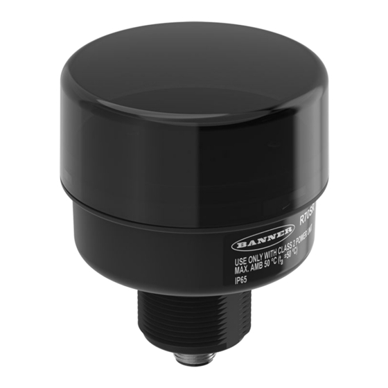
R70SR Serial Data Radios are compact, industrial, low-power wireless communications devices
used to extend the range of serial communications networks. The Serial Data Radios are available in two
frequencies, 900 MHz and 2.4GHz, and are fitted with M12 quick disconnect connectors for fast deployment.
• RS-485 serial communication
• Star or tree network topology configuration
• DIP switches select operational modes
• Frequency Hopping Spread Spectrum (FHSS) technology ensures reliable data delivery
• Self-healing, auto-routing radio frequency network with multiple hops to extend the network's range
For additional information, updated documentation, and a list of accessories, refer to Banner Engineering's
website, www.bannerengineering.com.
Frequency
900 MHz ISM Band
2.4 GHz ISM Band
Figure 1. Binding button, LEDs, and DIP switches
21 March 2022
Transmit Power
1 Watt
65 mW (100 mW EIRP)
Sure Cross Installation Guide
Binding button
LEDs
DIP
switches
(p/n
224673
Advertisement
Table of Contents

Related Manuals for Banner Sure Cross R70SR Series


Summary of Contents for Banner Sure Cross R70SR Series
- Page 1 • Frequency Hopping Spread Spectrum (FHSS) technology ensures reliable data delivery • Self-healing, auto-routing radio frequency network with multiple hops to extend the network's range For additional information, updated documentation, and a list of accessories, refer to Banner Engineering's website, www.bannerengineering.com.
-
Page 2: Open The Cover
Sure Cross ® R70SR Serial Data Radio For parameters not set using the DIP switches, use the configuration software to make configuration changes. For parameters set using the DIP switches, the DIP switch positions override any changes made using the configuration software. Open the Cover If the R70SR is in the locked position, the arrow on the cover is above the notch on the base. -
Page 3: Apply Power
Sure Cross ® R70SR Serial Data Radio In this simple cable replacement application with repeater, the radio system still knows all data originating at one end must be transmitted to the other end. In this application, there are no serial devices connected to the repeater(s). The system still corrects for transmission problems, but it takes time to repeat the message. -
Page 4: Master Led Behavior
Sure Cross ® R70SR Serial Data Radio 5-pin M12 Male Connector Wire Color Wiring Description Brown (bn) 10 to 30 V DC White (wh) RS-485 / D1 / B / + Blue (bu) DC common (GND) Black (bk) RS-485 / D0 / A / - Gray (gy) No connection Bind the R70SR Serial Data Radio to Form a Network... -
Page 5: Specifications
Interface search for the complete instruction manual Two bi-color LED indicators Certifications One button (under the small round cover) Construction Banner Engineering Europe Park (CE/UKCA approval only Lane, Culliganlaan 2F bus 3, 1831 applies to 2.4 GHz Diegem, BELGIUM models) - Page 6 Sure Cross ® R70SR Serial Data Radio Dimensions All measurements are listed in millimeters, unless noted otherwise. Figure 6. Dimensions for the R70SR 33.3 mm [1.31”] 20.9 mm [0.82”] M30 x 1 24.9 mm [0.98”] M12 x 1 8 mm [0.32”] Ø70 mm [2.76”]...
- Page 7 This device has been designed to operate with the antennas listed on Banner Engineering’s website and having a maximum gain of 9 dBm. Antennas not included in this list or having a gain greater that 9 dBm are strictly prohibited for use with this device.
-
Page 8: Banner Engineering Corp Limited Warranty
Banner Engineering Corp. warrants its products to be free from defects in material and workmanship for one year following the date of shipment. Banner Engineering Corp. will repair or replace, free of charge, any product of its manufacture which, at the time it is returned to the factory, is found to have been defective during the warranty period.
Need help?
Do you have a question about the Sure Cross R70SR Series and is the answer not in the manual?
Questions and answers