Advertisement
Quick Links
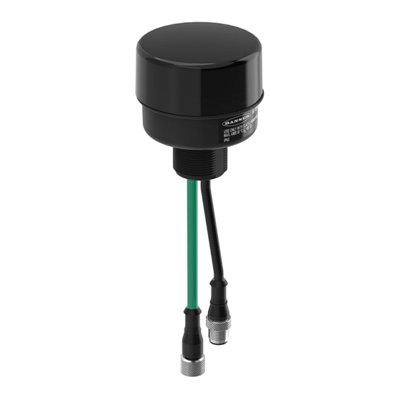
R70ER Ethernet Data Radio
R70ER Features
The Sure Cross R70ER Ethernet Data Radio is a compact, industrial, communication device used to create point-to-multipoint configurations
of wireless Ethernet networks. The R70ER is available in two frequencies, 900 MHz and 2.4 GHz, and is fitted with D-Code M12 quick
disconnect connectors for fast deployment.
Models
Models
R70ER9MQ
R70ER2MQ
Quick Start Guide
Set Up Your R70ER Radio Network
Each radio network should include one controller/primary radio and several repeater or peripheral radios. To set up and install your wireless
data radio network, follow these steps:
1.
Before installing your Ethernet data radios, first verify that your Ethernet devices work.
a.
Connect your devices using an Ethernet cable.
b.
Configure the IP addresses of your devices and use a ping test with Ethernet cables to verify the connectivity before
installing the radios.
This verifies the devices are configured correctly before replacing the cabled connection with a wireless connection.
2.
Configure the DIP switches of the R70ER.
3.
Apply power to all devices.
4.
Form the wireless network by binding the repeater and peripheral radios to the controller/primary radio.
5.
Observe the LED behavior to verify the devices are communicating with each other.
6.
Verify the Ethernet devices work wirelessly.
a.
Remove power to the R70 devices.
b.
Connect your Ethernet devices to the R70 Ethernet Radios and apply power.
c.
Run a ping test to confirm data is moving correctly through the wireless network.
Original Instructions
July 07, 2023
•
Star or tree network topology configuration
•
DIP switches select operational modes
•
No IP address configuration is required
•
Frequency Hopping Spread Spectrum (FHSS) technology ensures reliable data delivery
•
Self-healing, auto-routing radio frequency network with multiple hops to extend the network's
range
•
Advanced Encryption Standard (AES) using a 256-bit cryptographic key
For additional information, updated documentation, and a list of accessories, refer to Banner Engineering's
website, www.bannerengineering.com.
Frequency
900 MHz ISM Band
2.4 GHz ISM Band
© Banner Engineering Corp.
Transmit Power
500 mW
65 mW (100 mW EIRP)
p/n: 226574 Rev. B
226574
Advertisement

Subscribe to Our Youtube Channel
Related Manuals for Banner R70ER


Summary of Contents for Banner R70ER
- Page 1 Frequency Hopping Spread Spectrum (FHSS) technology ensures reliable data delivery • Self-healing, auto-routing radio frequency network with multiple hops to extend the network's range • Advanced Encryption Standard (AES) using a 256-bit cryptographic key For additional information, updated documentation, and a list of accessories, refer to Banner Engineering's website, www.bannerengineering.com. Models Models Frequency Transmit Power ...
-
Page 2: Configure The Dip Switches
R70ER Ethernet Data Radio Configuration Instructions R70ER Buttons and LEDs Binding button, LEDs, and DIP switches Binding Button Configure the DIP Switches In any radio network, there is one controller (master) radio and there can be many peripheral (slave) radios. Before changing the DIP switch positions, disconnect the power. Any changes made to the DIP switches are not recognized until after power is cycled to the device. ... - Page 3 R70ER Ethernet Data Radio Transmit Power Levels—The 900 MHz radios transmit at 500 mW (27 dBm) or 250 mW (24 dBm). The 250 mW mode reduces the radio's range but improves the battery life in short-range applications. For 2.4 GHz models, this DIP switch is disabled. The transmit power for 2.4 GHz is fixed at about 65 mW EIRP (18 dBm). Star Topology—To configure your radios as a star topology, set one radio to be the controller (DIP switch 1 ON). Set all the other radios to be peripheral radios. XML Behavior—The R70 Ethernet radio is programmed similarly to a DXM Controller and uses a standard XML configuration file to define its settings. For troubleshooting purposes, or advanced use cases, the XML can be bypassed when the device is turned on. With the XML bypassed, the R70 will receive its own IP address, either fixed or through DHCP, according to the DIP switch settings. ...
- Page 4 Black (bk) Reserved Bind the R70ER Ethernet Radio to Form a Network To create your network, bind the R70 to the designated controller/primary radio. Binding the radios ensures all radios within a network communicate only with the other radios within the same network. The data radio controller/primary automatically generates a unique binding code when the radio controller enters binding mode. This code is transmitted to all radios within range that are also in binding mode.
-
Page 5: Installing Your Sure Cross® Radios
R70ER Ethernet Data Radio Repeat steps 3 through 5 for as many radios as are needed for your network. On the controller/primary radio: After all radios are bound, double-click the binding button to exit binding mode. The network begins to form after the controller/primary data radio exits binding mode. On the controller/primary radio: Re-install the cover to protect the button and radio board. Child Radios Synchronize to the Parent Radios The synchronization process enables a Sure Cross® radio to join a wireless network formed by a controller/primary radio. A simple point-to- point network with one controller/primary radio and one peripheral radio synchronizes quickly after power up; larger MultiHop networks may take a few minutes to synchronize. First, all radios within range of the controller radio wirelessly synchronize to the controller radio. These radios may be repeater radios or peripheral radios. ... - Page 6 R70ER Ethernet Data Radio 900 MHz Compliance Average Current for 2.4 GHz Radios (1500 byte packets at 50 ms Radio module is indicated by the product label marking intervals Contains FCC ID: UE3RM7023: FCC Part 15, Subpart C, Client Mode: 0.035 A at 12 V; 0.02 A at 24 V 15.247...
- Page 7 R70ER Ethernet Data Radio Dimensions for the R70ER 20.9 mm [0.82”] M30 x 1.5 M12 x 1 (male) M12 x 1 (female) R70ER Accessories 4-Pin Threaded M12 Cordsets—Double Ended Model Length Style Dimensions Pinout MQDEC-401SS 0.31 m (1 ft) 40 Typ. [1.58"] MQDEC-403SS 0.91 m (2.99 ft) MQDEC-406SS 1.83 m (6 ft) ...
- Page 8 R70ER Ethernet Data Radio Continued from page 7 4-Pin Threaded M12 Cordsets—Double Ended Model Length Style Dimensions Pinout MQDEC-403RR 0.9 m (2.9 ft) [1.26"] MQDEC-406RR 1.8 m (5.9 ft) [1.18"] MQDEC-412RR 3.6 m (11.8 ft) Male Right-Angle / Female Right-Angle M12 x 1 ø 14.5 [0.57"] MQDEC-420RR 6.1 m (20 ft) 4-Pin Threaded M12 Cordsets—Single Ended Model Length Style ...
- Page 9 IMPORTANT: Please download the complete Sure Cross R70ER Ethernet Data Radio technical documentation, available in multiple languages, from www.bannerengineering.com for details on the proper use, applications, Warnings, and installation instructions of this device. IMPORTANT: Por favor descargue desde www.bannerengineering.com toda la documentación técnica de los Sure Cross R70ER Ethernet Data Radio, disponibles en múltiples idiomas, para detalles del uso adecuado, aplicaciones, advertencias, y las instrucciones de instalación de estos dispositivos. IMPORTANT: Veuillez télécharger la documentation technique complète des Sure Cross R70ER Ethernet Data Radio sur notre site www.bannerengineering.com pour les détails sur leur utilisation correcte, les applications, les notes ...
-
Page 10: Banner Engineering Corp Limited Warranty
Banner Engineering Corp. warrants its products to be free from defects in material and workmanship for one year following the date of shipment. Banner Engineering Corp. will repair or replace, free of charge, any product of its manufacture which, at the time it is returned to the factory, is found to have been defective during the warranty period.
Need help?
Do you have a question about the R70ER and is the answer not in the manual?
Questions and answers