Table of Contents
Advertisement
Advertisement
Table of Contents
Troubleshooting

Subscribe to Our Youtube Channel
Related Manuals for Mindray VS-800


Summary of Contents for Mindray VS-800
- Page 1 VS-800 Vital signs monitor Service Manual...
- Page 3 Mindray, nor the rights of others. Mindray does not assume any liability arising out of any infringements of patents or other rights of third parties.
- Page 4 Once being polluted by liquid, they must be thoroughly dried. If to further remove the pollution, please contact your biomedical department or Mindray. It is important for the hospital or organization that employs this equipment to carry out a reasonable maintenance schedule.
- Page 5 ■ Assembly operations, extensions, re-adjusts, modifications or repairs are carried out by persons other than those authorized by Mindray. ■ The VS-800 is not used in accordance with the instructions for use, or the electrical installation of the relevant room does not comply with NFPA 70: National Electric...
- Page 6 Return Policy Return Procedure In the event that it becomes necessary to return a unit to Mindray, the following procedure should be followed: Obtain return authorization. Contact the Mindray Service Department and obtain a Customer Service Authorization (Mindray) number. The Mindray number must appear on the outside of the shipping container.
- Page 7 Safety Precautions 1 . Meaning of Signal Words DANGER, WARNING CAUTION In this manual, the signal words , and are used regarding safety and other important instructions. The signal words and their meanings are defined as follows. Please understand their meanings clearly before reading this manual. Signal word Meaning Indicates an imminently hazardous situation which, if not...
- Page 8 WARNING: Do not connect this system to outlets with the same circuit breakers and fuses that control current to devices such as life-support systems. If this system malfunctions and generates an overcurrent, or when there is an instantaneous current at power ON, the circuit breakers and fuses of the building’s supply circuit may be tripped.
-
Page 9: Table Of Contents
Content Content Chapter 1 Monitor Description..................1-1 1.1 Intended Use......................1-1 1.2 Environmental Specifications ..................1-1 Chapter 2 Principles of Operation ..................2-1 2.1 General ........................2-1 2.2 Hardware Description....................2-2 2.3 Software Description ....................2-13 2.4 System parameters ....................2-17 Chapter 3 Chapter Specifications..................3-1 3.1 Type of Monitor ......................3-1 3.2 Specifications of Monitor ....................3-1 Chapter 4 Machine Disassembly/assembly and troubleshooting ........4-1 4.1 Disassembly/assembly Figure..................4-1... - Page 10 Content For your notes...
-
Page 11: Chapter 1 Monitor Description
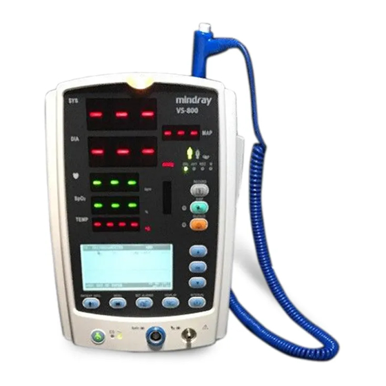
Monitor Description Monitor Description Chapter 1 1.1 Intended Use This Monitor is intended for monitoring the patient’s vital signs including Non-invasive Blood Pressure (NIBP), Pulse Oxygen Saturation (SpO2), Pulse Rate (PR) and Temperature (TEMP) for single adult, pediatric and neonatal patient. This Monitor is intended for use in the health-care institutions such as Outpatient Clinics, Emergency Departments, Medical Floors, Clinics and Nursing Departments. - Page 12 Monitor Description 1.2.4 Power Requirements Voltage: AC 100-240 V, 50/60 Hz 70VA Power: 1.2.5 Rechargeable Battery Rechargeable lead-acid battery, 2.3 Ah, 12V Minimum of 260min: The monitor runs on power supplied by the new fully-charged battery in the following conditions: Ambient temperature: 25 ºC Monitor configuration: SpO (Continuous measurement) and NIBP (one auto NIBP...
-
Page 13: Chapter 2 Principles Of Operation
Connection cables Figure 1 System structure As shown in Figure 2-1, the VS-800 Vital Signs Monitor consists of • 4 mechanical parts: host, recorder, TEMP module chamber and rechargeable battery chamber; • 6 hardware parts: main board, key&displays board, parameter boards, recorder board, connection cables and power board;... -
Page 14: Hardware Description
Mindray SpO2 module does not require the isolation power board. Figure 2 Structure of hardware Note1: The TEMP module mentioned in this manual is reserved for future use. The hardware connections of the VS-800 Vital Sings Monitor are as shown in Figure 2-3:... - Page 15 The functions and operation principles of the VS-800 hardware parts are detailed respectively in the following sections.
- Page 16 Principles of Operation 2.2.1 Main Board Principle diagram 2.2.1.1 Watchdog E 2PROM Ethernet RTL8201 Serial port 0 RS232 Nurse Call RS232 IC Audio process circuit Speaker Serial port 1: NIBP SDRAM Flash Serial port 2: SpO2 FPGA Serial port 3: Temp 1.5V Serial port 4: Recorder Linear power...
- Page 17 Principles of Operation 2.2.1.3 Units of main board 2.2.1.3.1 FPGA FPGA is used for: Controlling STN-LCD The PFGA drives the display of the monochromatic STN-LCD module, including the RAM and displaying sequence; it communicates with the key&displays board CPLD. The FPGA transmits data displayed by LEDs and receives key information by Means of communicating with keypad CPLD through synchronous serial port.
- Page 18 Principles of Operation 2.2.1.3.6 NURSE CALL connector 2.2.1.3.7 The NURSE CALL connector controls the NURSE CALL signal by using an I/O port extended by the FPGA. 2.2.2 Power Board 2.2.2.1 General The power board converts the power input (from AC mains or battery) to different working voltages for other boards;...
- Page 19 Principles of Operation The 16.8V DC output is protected against over-voltage and over-power; the 12V and 3.3V DC outputs are protected against over-voltage, short-circuit and over-current; the 5V DC output is protected against over-voltage and short-circuit. 2.2.3 Key&displays board 2.2.3.1 General The key&displays board provides the user’s interface.
- Page 20 Principles of Operation 2.2.3.2.2 LED There are Six groups of 7-segment digit display on the key&displays board. They are used for displaying the systolic pressure, diastolic pressure, mean pressure/cuff pressure, SpO , PR and Temp; every group is of 3 digits. The signal is transmitted from the main board FPGA to the CPLD, and is displayed by the 7-segment digit displays driven by the CPLD scanning.
- Page 21 Principles of Operation 2.2.4 SpO Module 2.2.4.1 General The SpO module provides the function of measuring the Pulse Oxygen Saturation (SpO 2.2.4.2 Principle diagram Figure 7 Operation principle of the SpO2 module 2.2.4.3 Principle The SpO measurement principle: 1. Collecting the light signal of the red light and infrared transmitting through the finger or toe which is pulsing;...
- Page 22 Principles of Operation 2.2.4.3.3 A/D The A/D conversion part converts the analog signal to the digital signal, and then sends it to CPU for further processing. 2.2.4.3.4 D/A The D/A conversion part converts the digital signal received from CPU to the analog signal, and provides the control signal for the Led Drive Circuit and SPO2 Signal Process Network.
- Page 23 Principles of Operation The NIBP is measured based on the pulse vibration principle. Inflate the cuff which is on the forearm till the cuff pressure blocks the arterial blood, and then deflate the cuff according to a specified algorithm. While the cuff pressure is decreasing, the arterial blood has pulses, which are sensed by the pressure transducer in the cuff.
- Page 24 Principles of Operation 2.2.6 TEMP Module General This module provide the function of measuring the temperature. Schematic diagram 图 2-1 TEMP schematic diagram Principle Normally, the sensor used for measuring temperature is a thermistor. The resistance of a given thermistor is nonlinearly relative to the temperature. Thus, the resistance of a thermistor can be conversed into temperature.
-
Page 25: Software Description
2.3 Software Description 2.3.1 General 2.3.1.1 Composition of software The VS-800 software consists of the system software, module software, upgrade software and printer software. Besides the system software, all the other software components are universal. Therefore, the following sections will emphasize on the requirements of the system software. For other software, only references are provided. - Page 26 Patient Keypad Thermal recorder Nurse Figure 9 Function of system software The VS-800 software provides the following functions: Transmitting/receiving data to/from modules; Displaying parameters, plethysmograms and trend data; Rising alarms; Controlling the recorder; Reviewing patient history data; Network function;...
- Page 27 Principles of Operation Displaying measurement results with LEDs; 10 Outputting data to PC for permanent storage and data printing. 2.3.2.2 Functions of system software 2.3.2.2.1 Power management The system detects the battery and battery volume automatically, and power LED gives status of battery. The system detects the voltage (12V) of the main board periodically.
- Page 28 Principles of Operation to enter the standby status. In the standby status, press any key on the front panel of the monitor or withdraw the temperature probe from the probe sheath to exit the standby status. The EXIT STANDBY dialog box appears, prompting “Enter monitoring state?” Select YES to exit the Standby status and enter the monitoring status.
-
Page 29: System Parameters
Principles of Operation monitor can store 1 group of user default configuration for each patient type. Storage of trend data: In the full configuration, the non-volatile data include trend data of all parameters: systolic pressure, mean pressure, diastolic pressure, PR, SpO , measurement time and patient ID. - Page 30 Principles of Operation the A/D converter, and finally processed by the MCU. After that, the systolic pressure, diastolic pressure and mean pressure can be obtained. For neonates, pediatric and adults, it is necessary to select the cuffs of a proper size to avoid possible measurement errors. In the NIBP measurement, there is a protection circuit used to protect patient from over-high pressure.
- Page 31 Principles of Operation 2.4.3 TEMP Body temperature can be taken with two different methods according to the temperature probe used. One method is direct measurement with which the temperature is measured by thermal equilibrium. Therefore, thermistor, platinum resistance or mercury can be used in the temperature probe.
- Page 32 Principles of Operation For your notes 2-20...
-
Page 33: Type Of Monitor
Operating ambient temperature 0℃ - 40℃ Storage temperature -20℃ - 60℃ C - +40 C(50 F -104 F) (Mindray TEMP module) 3.2.2.2 Relative Humidity Operating relative humidity 15% - 95% (non-condensing) Transportation and storage relative humidity 10% - 95% (non-condensing) - Page 34 Product Specifications 3.2.2.3 Power Requirements Voltage: AC 100 - 240 V, 50/60 Hz (± 3 Hz) Power: 70VA Switch : Standby 3.2.3 Specifications of Display LCD display Dot matrix: 320×160 Dot pitch: 0.24×0.24 Dot size: 0.225×0.225 LCD type: FSTN LCD Polarity: Positive Transmission mode:...
- Page 35 Product Specifications Maximum load current ≤2A Connection resistance <1Ω Isolation voltage >1500V AC Network interface For connection to the Central Monitoring Network, software upgrade and data export 3.2.5 Battery No. of batteries: Battery type: Sealed lead-acid battery or lithium ion battery Time to shutdown at low battery power: 5-15min after the first low-battery alarm (a new fully-charged battery should be used)
- Page 36 Product Specifications Paper length Paper speed 25 mm/s, ±5% Record mode The recorder should support 3 record modes: Recording current trend data being displayed on the LCD of the current patient Recording all patient trend data Recording waveform graphs continuously in real time 3.2.7 Review Trend review Storage of trend data:...
- Page 37 Product Specifications 3.2.8 NIBP Measuring method Automatic oscillometry Mode of operation Manual/Automatic/Continuous Measuring interval for automatic mode: 1,2,3,4,5,10,15,30,60,90,120,180,240,480min Measuring time for continuous mode: 5min Maximum measurement cycle Adult/pediatric: 180s Neonate: Range 40 - 240 bpm ±2 bpm or ±2%, whichever is the greater Accuracy Resolution 1bpm...
- Page 38 Product Specifications ±5mmHg Max. mean error Max. standard error 8mmHg Software over-pressure protection: The over-pressure detection is controlled by software. Once the cuff pressure exceeds the threshold, the software enables the system to deflate the cuff. Adult 300 mmHg Pediatric 243mmHg Neonate 150 mmHg...
- Page 39 Product Specifications PR (bpm) Response time Under the condition that the PR is 75BPM and the mean time is 8s, the maximum response time for the SpO value to increase from 60% to 95% is 20s. 3.2.9.2 9006 SpO2 Range: 0 - 100% Resolution: Accuracy...
- Page 40 Product Specifications Range and accuracy for Range Accuracy PR measurement: 20 - 250 BPM ±3 BPM 251 - 300 BPM Undefined Updating cycle of SpO values: 3.2.10 TEMP Specification Parameter Specification Displayed parameter TEMP Measurement range 25 - 44 ºC(77 - 111.2 ºF) Resolution In MONITOR mode: 0.1ºC (0.2 ºF) In MONITOR mode: 25 - 32 ºC (77 - 89.6 ºF): ±0.2 ºC (±0.3...
-
Page 41: Chapter 4 Machine Disassembly/Assembly And Troubleshooting
Machine Disassembly/Assembly and Troubleshooting Chanpter4 Machine Disassembly/Assembly and Troubleshooting 4.1 Disassembly/Assembly Figure 4.1.1 Host Assembly Figure 1 Host assembly Std. Code Name & Spec. Qty. 6006-30-39446 Front housing component 6006-30-39401 Master bracket component (lead-acid) 6006-30-39447 Rear housing component M04-000505--- Cross pan head screwM3X20 M04-004012--- Cross pan head screw with washer M3X6... - Page 42 Machine Disassembly/Assembly and Troubleshooting 4.1.2 Master bracket (lead-acid battery) assembly Figure 2 Master bracket (lead-acid battery) assembly Std. Code Name & Spec. Qty. 6006-20-39367 Main bracket (lead-acid battery) 6006-30-39448 Lead-acid battery assembly M04-004015--- Gasketed cross-head screw M3*8 6006-20-39385 Speaker & connection cables 6006-20-39379 Washer of speaker 6006-20-39464...
- Page 43 Machine Disassembly/Assembly and Troubleshooting M04-004012--- Gasketed cross-head screw M3*6 6006-20-39478 Lead-acid battery power board M04-000106--- Screw M3X7+8-6 M04-011002--- M3 nut with external-tooth spring washer 0000-10-10996 finger-like beryllium-copper spring plate92-047 6006-20-39387 Fan & connection cables 6006-20-39373 Fan support M04-002005--- Cross-head sunk screw M3*12 6006-20-39434 Fan washer 0509-20-00098...
- Page 44 Machine Disassembly/Assembly and Troubleshooting 4.1.3 Master bracket (lithium) assembly Figure 3 Master bracket (lithium) assembly Std. Code Name & Spec. Qty. 6006-20-39416 Master bracket (lithium) 6006-30-39449 Lithium battery component M04-004012 Gasketed cross-head screw M3*6 6006-20-39385 Speaker and connection line 6006-30-39379 Speaker press plate...
- Page 45 Machine Disassembly/Assembly and Troubleshooting 6006-30-39464 Insulating plate for power board M04-011002--- M3 nut, with spring washer 6006-20-39393 Lithium power board M04-000106--- Screw M3X7+8-6 0000-10-10996 EMI finger-shape beryllium-copper spring plate92-047 6006-20-39387 Fan and connection line 6006-20-39373 Fan rack M04-002005--- Cross flat countersunk screwM3X12 6006-20-39434 Fan washer 0509-20-00098...
- Page 46 Machine Disassembly/Assembly and Troubleshooting 4.1.4 Front shell assembly Figure 4 Front shell assembly Std. Code Name & Spec. Qty. 6006-20-39358 front cover 6006-20-39520 Waterproof bar 6006-20-39372 silicon button 6006-20-39431 silicon keypad press plate M04-021000--- flat washer 6006-20-39488 dust panel1 6006-20-39482 LED shade 6006-20-39354 keypad...
- Page 47 Machine Disassembly/Assembly and Troubleshooting 0000-10-10997 6006-20-39487 dust panel2 M04-051003--- cross pan head screw, pointless, tail-cut, self-tapping 6006-20-39415 silcon power button 6006-20-39376 battery door tape 6006-20-39359 battery door M04-003905--- cross head screw, pointless, self-tapping M04-021024--- Large flat washer GB 96 3 0010-20-12194 pneumatic connector assembly 6006-20-39587...
- Page 48 Machine Disassembly/Assembly and Troubleshooting Std. Code Name & Spec. Qty. 6006-20-39351 Back shell 6006-20-39374 Label (Chinese) M04-002505--- Cross head screw M3x6 6006-30-39572 Predictive TEMP module 6006-20-39375 Foot cushion 6006-20-39418 Speaker cushion PT3X6n 6006-20-39369 Support for recorder M04-003905--- Tapping screw PT3X6 M04-000603--- External teeth washer GB862.1 3 M04-003105---...
- Page 49 Machine Disassembly/Assembly and Troubleshooting 6006-30-39427 Lithium battery socket board M04-030030--- Hexagon stud M3X12 9201-20-36038 Battery thrust spring M04-000605--- Cross head screw M3X8 M04-051026--- Stainless socket head hexagon screw M3X10 M90-000002-03 Insulated washer Φ3X0.5 4.1.7 Lead-acid battery assembly Figure 7Lead-acid battery assembly Std.
- Page 50 Machine Disassembly/Assembly and Troubleshooting 9000-20-07286 spring M04-011002--- M3 nut, with spring washer M04-051060--- cross pan head screw, pointless, tail-cut, self-tapping M2X8 M04-021000--- Washer GB 97.2 2.5 4.1.8 MASIMO SpO board assembly Figure 8MASIMO SpO board assembly Std. Code Name & Spec. Qty.
- Page 51 Machine Disassembly/Assembly and Troubleshooting M04-000104--- Spring washer GB93 3 M04-000106--- Screw M3X7+8-6 6006-20-39366 mount bracket M04-002505--- Cross-head screw M3*6 4.1.9 TEMP assembly Std. Code Name & Spec. Qty. 6006-20-39363 TEMP module housing 1 M04-003905--- Tapping screw PT3X6 6006-20-39364 TEMP module housing 1 M04-002505--- Cross head screw M3X6 6006-20-39569...
-
Page 52: Inter-Board Connections
4.2 Inter-board Connections 4.2.1 List of Connection Cables 4.2.1.1 Signal lines Name Material number Graphic connection relations MINDRAY 9006 SPO2 signal line 6006-21-39390 See the figure below. NELLCORE SPO2 signal line 6006-21-39392 See the figure below. MASIMO SPO2 signal line 6006-21-39391 See the figure below. - Page 53 Machine Disassembly/Assembly and Troubleshooting 4.2.1.3 Connection Cable Figure Figure 9MINDRAY 9006 SPO2 Signal Line Figure 10MASIMO SPO2 Signal Line Figure 11NELLCORE SPO2 Signal Line Figure 12Main Board Power Cord Figure 13Recorder Signal Line 4-13...
- Page 54 Machine Disassembly/Assembly and Troubleshooting Figure 14SpO2 Module Connection Cables Figure 15LCD Signal Line Figure 16Keypad Signal Line Figure 17Keypad Power Connection Cables Figure 18Speaker and Connection Cables 4-14...
- Page 55 Machine Disassembly/Assembly and Troubleshooting Figure 19Power Board AC Input Connection Cables Figure 20Fan and Connection Cables Figure 21Power Board-to-Battery Backplate Connection Cables (Lithium) Figure 22Power Board-to-Battery Backplate Connection Cables (Lead-acid) 4-15...
-
Page 56: Troubleshooting
Machine Disassembly/Assembly and Troubleshooting Figure 23Recorder Power Cord Figure 24NIBP Module Connection Cables Figure 25 Isolation power board to the TEMP module connection cables 4.3 Troubleshooting 4.3.1 Cannot start 4-16... - Page 57 Machine Disassembly/Assembly and Troubleshooting Cannot start Check if the AC indicator is lit Check if the power Check the keypad-to-main board signal line for fault; supply is normal Check the keypad-to-power board signal line for fault; Check the keyboard for fault Check the main board for fault;...
- Page 58 Machine Disassembly/Assembly and Troubleshooting Check the speaker connection cables; Replace the speaker; Replace the main board. 4.3.5 Cannot Print Check if the software has recorder-related alarms. If yes, eliminate them; Check if the recorder indicator is lit; If not, check the recorder signal input connection cables; Check the recorder power input connection cables (including the recorder power board);...
- Page 59 Machine Disassembly/Assembly and Troubleshooting 4.3.9 TEMP Module Works Abnormally Check that the temperature probe is correct; Check that the communication cable is in good condition; Check that the TEMP module self-check properly; Otherwise, replace the TEMP module. 4-19...
- Page 60 Machine Disassembly/Assembly and Troubleshooting For your notes 4-20...
-
Page 61: Chapter 5 Machine Test And Material List
Chanpter5 Machine test and Material List 5.1 Test Procedure Connect the simulators, power and fixture to the VS-800 and power it on. The LED and LCD modules should display correctly 5.1.1 Button Function Test Press each button on the keypad. The VS-800 should give corresponding response and perform corresponding function. - Page 62 1. Print SpO2 graph. The recorder should print correctly and the printed results should be clear and consistent. If set such faults such out of paper, etc., corresponding prompts should be given. After the fault is removed, the VS-800 should be able to work correctly.
-
Page 63: Material List
6006-20-39384 LCD signal line 6006-21-39385 Speaker and connection cables 6006-21-39386 Power board AC input connection cables 6006-20-39387 Fan and connection cables 6006-20-39388 Power board-to-battery back-plate connection cables (lithium) 6006-20-39389 Power board-to-battery back-plate connection cables (lead-acid) 6006-21-39390 SPO2 signal line (Mindray) - Page 64 Bolster plate for middle LED (bottom) 6006-20-39433 Bolster plate for small LED (right) 6006-20-39434 Fan press plate 6006-20-39435 Recorder cap 6006-20-39436 VS-800 Operation Manual (Chinese) 6006-20-39437 VS-800 Operation Manual (English) 6006-20-39438 VS-800 Maintenance Manual (Chinese) 6006-20-39439 VS-800 Maintenance Manual (English) 6006-20-39440...
- Page 65 Overlay of front housing (English /SpO2 6006-20-39466 only) 6006-30-39467 Front housing assembly (SpO2 only) 6006-30-39468 Packaging material 6006-30-39469 NIBP module package 6006-30-39470 SPO2 module package (MINDRAY) 6006-30-39471 SPO2 module package (MASIMO) 6006-30-39472 SPO2 module package (NELLCOR) 6006-30-39473 Label package (domestic) 6006-30-39474 Label package (international) 6006-30-39475...
- Page 66 CPLD configuration code 6006-20-39502 LCD backplate 6006-30-39503 Label package (for domestic bid) 6006-20-39504 Alarm Overlay 6006-20-39509 Overlay of NIBP bracket 6006-20-39510 VS-800 CD label(english) 6006-20-39511 VS-800 CD label(english) 6006-20-39512 Insulating plate(lithium) for keypad 6006-20-39513 external packing box 6006-30-39514 CD assembly(chinese) 6006-30-39515 CD assembly(English)...
-
Page 67: Nibp Calibration Method
Machine test and Material List 5.3 NIBP Calibration Method Figure 1 NIBP Static Pressure Calibration Method Calibration method: Increase the pressure at intervals of 50mmHg(6.7kPa). The maximum difference between the monitor and calibrator at any pressure point within the measurement range does not exceed ±3mmHg (±0.4kPa). - Page 68 Machine test and Material List For your notes...
-
Page 69: Chapter 6 Maintenance And Cleaning
In case of any indication of functional damage, stop using the monitor, and contact bio-medical engineers of the hospital or Mindray service engineers immediately. 6.1.2 Routine Inspection An overall inspection, including the functional safety inspection, must be performed on the monitor by qualified personnel for every 6-12 months or after maintenance each time. -
Page 70: General Cleaning
Be sure to shut down the system and disconnect all power cords from the outlet before cleaning the equipment or accessories. The VS-800 Vital Signs Monitor should be free from dust. The exterior surface and LCD should be cleaned with non-corrosive cleaning solutions, such as the diluted soap water and water. -
Page 71: Contact Information For Maintenance And Technical Support
Following are examples of cleaning/Disinfection solutions: Alcohol based (Ethanol 70%, Isopropanol 70%) aldehyde based 6.5 Contact Information for Maintenance and Technical Support Address Mindray Building, Keji 12th Road South, Hi-Tech Industrial Park, Nanshan, Shenzhen 518057, P.R. China Manufacturer Customer Service, Shenzhen Mindray Bio-Medical Electronics Co., Ltd. - Page 72 Maintenance and Cleaning FOR YOUR NOTES...
- Page 74 P/N: 6006-20-39439(2.0)
Need help?
Do you have a question about the VS-800 and is the answer not in the manual?
Questions and answers