Advertisement
Quick Links
Advertisement

Related Manuals for TCL TRF-315W


Summary of Contents for TCL TRF-315W
- Page 1 Refrigerator Service Manual TRF-315W TCL Home Appliances (HeFei) Co., Ltd.
- Page 2 Contents 1.Product introduction, Technical Parameters 2.Exploded View of Product Structure 3.Product operation rules 4.Refrigeration system and electrical control 5.Maintenance guide...
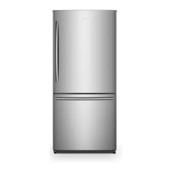
- Page 3 Product introduction Taking TRF-315WEA + (internal display) prototype as an example, it is an air-cooled double door refrigerator, the upper part of which is the refrigerating chamber, and the lower part is the freezer chamber. Refrigerating top light Door of refrigerating chamber Refrigerating door bottle holder Refrigerating shelf Fruit and vegetable box cover...
- Page 4 Exploded View of Product Structure The schematic diagram showing the structure of TRF-315WEA + refrigerator is as follows:...
- Page 5 Detail list of parts Serial number Description of the material Quantity Refrigerating chamber upper end cover and through-holes decorative cover Display control board assembly Refrigerating foam door body Freezing foam door body Refrigerating door gasket assembly Freezing door gasket assembly Refrigerating bottle holder Freezing glass shelf Freezing glass shelf...
- Page 6 Product operation rules Operating instructions (TRF-315WEA + internal display) Powered on for the first time The refrigerator will run in Gear 5 when it is powered on for the first time. Gear adjustment Press "+" key or "-" repeatedly. The refrigerator gear will cycle between "02" → "04" → "05" → "06" → "08" → "02".
- Page 7 Operating instruction (TRF-315WEXA+) Powered on for the first time The refrigerator will run in Gear 5 when it is powered on for the first time. Child lock function When there is no key operation on the display screen within 30 seconds, the child lock function will automatically start and the screen saver mode of the display screen will be activated.
- Page 8 Energy saving mode Refer to "Gear adjustment" to set the "Energy saving" mode. In this mode, the refrigerator will run in Gear 6. Power off memory When power goes off, the instantaneous working state at the time of power off will be locked. After power on, it will still work according to the setting before power off.
- Page 9 Refrigeration system The refrigeration schematic diagram is as follows: Condenser Dry filter Dew-proof tube Capillary tube Finned-type evaporator Evaporation coil Compressor...
- Page 10 Schematic diagram for welding of pipelines in compressor compartment Solder joints for return-air Solder joints for compressor Solder joints for duct and return-air and evaporation coil evaporation coil and dew- Solder joints for transition duct proof tube condenser and dry filter Solder joints for dew-proof tube...
- Page 11 Schematic Diagram of Freezer chamber Welding position of freezing evaporator...
- Page 12 Compressor Wiring Diagram Compressor Sealed terminal Motor protector PTC relay Running capacitor Earth screw Relay cover Compressor connector socket Compressor terminal block II Crosshead self-tapping screw Compressor terminal block I...
- Page 13 Electrical control Schematic Diagram of Electrical Control Plug Refrigerating switch Overloading protector Freezing fan PTC relay Master control board Capacitor Refrigerating light Compressor Refrigerating sensor Ambient temperature sensor Defrosting heater Temperature fuse Defrosting sensor Temperature fuse...
- Page 14 Composition of electrical control system: 1. Compressor — refrigeration device; 2. Refrigerating light — used for lighting in refrigerating chamber; 3. Freezing fan — used for cooling capacity transmission and air circulation; 4. Steel tube heater — used to remove frosting on the surface of freezing evaporator; 5.
- Page 15 Control of components: (1) Compressor If refrigeration is required, turn on the compressor; if not, turn off the compressor; The downtime of the compressor must be more than 8 minutes before it can be started again; (2) Light When the refrigerating door is opened, the refrigerating light will be on. When the refrigerating door is closed, the refrigerating light will go out;...
- Page 16 Failure running program: When the temperature sensor for the freezer chamber fails, the refrigeration will proceed in the following chronological order: 25 minutes of refrigeration, and then 25 minutes of no refrigeration. When the ambient temperature sensor fails, the temperature will be controlled at 25℃. In case of communication failure, it will run in the gear before the failure.
- Page 17 Maintenance guide Before maintenance, it is necessary to know the actual usage of the user before taking corresponding measures User usage Guidance and handling Surrounding clearance: more than 10 cm at No clearance around the back and more than 30 cm at the top, keep it ventilated.
- Page 18 Composition of the top light assembly (internal display) Lamp holder Control board Back cover Display patch Lamp board Transparent lampshade...
- Page 19 Composition of the top light assembly (external display) 控制板 Control board Lamp holder Back cover Lamp holder 灯座 Display patch Lamp board Transparent lampshade...
- Page 20 Step I: Remove the 2 screws at the rear of the assembly State after the removal Step II: Pull down the top light from the rear as shown in the figure, and unplug the plug-in terminal...
- Page 21 Removal of the top light Step I: Connect the plug-in terminal, put the top light into the groove on the top of the refrigerator liner, and clamp the front claw into the liner first. Step II: Hold the back with your hands, and use two State after assembly 4.2*16 self-tapping screws to fix the screw holes as shown in the figure...
- Page 22 Composition of air duct assembly in refrigerating chamber Back of refrigerating Front of refrigerating air duct assembly air duct assembly Back of the cover plate of the refrigerating air duct Sealing foam IXPE Temperature sensor Damper regulating switch Air vent sealing foam EPDN Insulation Foam air duct...
- Page 23 Removal of refrigerating air duct assembly Step I: Remove the refrigerating air duct assembly from top to bottom Step II: Remove the refrigerating air duct assembly from the body of the refrigerator, as shown in the figure, and unplug the plug-in terminal...
- Page 24 Installation of refrigerating air duct assembly Step I: Connect the plug-in terminal shown in the figure, and put the refrigerating air duct assembly into the groove on the back of the refrigerator liner, and first assemble the lower end of the refrigerating air duct assembly with the refrigerator liner.
- Page 25 Composition of air duct assembly in freezing compartment Back of freezing air duct assembly Front of freezing air duct assembly...
- Page 26 Removal of freezing air duct assembly Step I: Pull the air duct out from the bottom and then remove Step II: Remove the freezing air duct assembly from the body of the refrigerator, as shown in the figure, unplug the plug-in terminal...
- Page 27 Installation of freezing air duct assembly Step I: Connect the plug-in terminal shown in the figure, and align the claws of the freezing air duct assembly with the slots. State after assembly Step II: Support the air duct from the bottom up, install the upper buckle first, then push the whole air duct inward, and clamp the buckle tightly.
- Page 28 The compressor does not work: Whether the refrigerating Whether the power plug is Whether the voltage is normal chamber light is on plugged in Make the voltage stable and normal Plug in the power plug Whether the compressor works Check whether the master Replace the master control board control board is normal Use a multimeter to test whether...
- Page 29 Excessive noise: Excessive noise Whether the ground is flat Keep the ground level Resonance with objects through collision Avoid collision with objects Whether the pipelines in the compressor Adjust the pipeline to avoid collision compartment collide with each other...
- Page 30 The compressor does not stop for a long time: The compressor does not stop for a long time Move it to a place with low ambient Whether the ambient temperature temperature is too high Whether the door of the Close the door of the refrigerator refrigerator is closed tightly tightly Whether the gear is appropriate...
Need help?
Do you have a question about the TRF-315W and is the answer not in the manual?
Questions and answers
Какова номинала используются датчики МК, ХК и температура с наружи?