Advertisement
Advertisement

Related Manuals for TCL TRF-520WEXA+


Summary of Contents for TCL TRF-520WEXA+
- Page 1 Refrigerator Service Manual TRF-520WEXA+ TCL Home Appliances (HeFei) Co., Ltd.
-
Page 2: Table Of Contents
Contents 1.Product introduction 2.Exploded View of Product Structure 3.Product operation rules 4.Refrigeration system and electrical control 5.Instructions for Disassembly of Components and Parts 6.Maintenance instructions... -
Page 3: Product Introduction
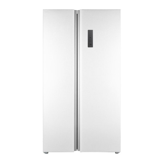
1.Product introduction TRF-520WEXDA+ is air-cooled side-by-side computer-temperature-control refrigerator, with freezer chamber on the left and refrigerating chamber on the right. The appearance modeling drawing is as follows:... - Page 4 Product features Smart computer-temperature-control, air-cooled and frost-free Adopt smart and convenient computer temperature control and visual operation, safe and efficient air-cooled frost-free system; Green and environmentally-friendly refrigerant Adopt CFC-free material, R600a green and environmentally-friendly material, 80% of the main materials can be recycled; Adopt the air blowing in the left and right direction, so the refrigeration is even;...
- Page 5 Product appearance...
- Page 6 Internal assembly of products Refrigerating air duct assembly Upper freezing air duct Lower freezing air assembly duct assembly...
- Page 7 Internal assembly of products Evaporator Defrosting heater Freezing fan motor Air swing motor assembly...
-
Page 8: Exploded View Of Product Structure
2. Exploded View of Product Structure... - Page 9 Detail list of cabinet parts Serial English Name Upper left Upper hinge left Upper hinge right Cold storage room air duct Cold air duct cover plate Upper right Main control panel cover Main control panel lamp shade LED lamp Compressor the drain Cold storage door seal assembly Cold storage glass shelf assembly...
- Page 10 Detail list of cabinet parts Cold storage drawer The compressor compartment rear cover Compressor Water connecting plate evaporation tube the lawer right hinge components Box assembly Lower hinge Bottle holder According to cover Bottle holder for freezer door Freezer door body Refrigerator door body water pans The freezer up duct...
-
Page 11: Product Operation Rules
3. Product operation rules The TRF-520WEXA+ display panel is as follows:... - Page 12 First time to electricity The first time to electricity, the cooling room runs at he 5℃ and the freezing room runs at the -18℃ The function of adjusting the temperature manually Temperature adjustment in cooling room(2℃~8℃) Under unlock status, long press “ ”...
- Page 13 Open refrigerator door over three minutes exit quick refrigerating function under quick refrigerating status.) Quick freezing function Under unlock status, repeatedly press “ ” key until the “ ” icon flashes. Stop key operation and wait for 5 seconds to enter quick freezing function of freezer compartment. Manually exit quick freezing function through the same operation.
- Page 14 Refrigerating close function Under unlock status, long press “ ” key for 3 seconds until the temperature icon switches to refrigerator compartment, press “ ” key to adjust temperature for refrigerator compartment. Stop key operation and wait for 5 seconds when the shift of refrigerator compartment is at "OF" to enter refrigerating close function.
- Page 15 Technical Parameters...
-
Page 16: Refrigeration System And Electrical Control
4. Refrigeration system and electrical control Condenser Filter drier Anti-condensation pipe Capillary tube Fin evaporator Compressor Evaporation coil... - Page 17 Schematic diagram of freezer chamber Evaporator outlet, connection Evaporator inlet, connection pipe for pipe for air return pipe capillary tubes Reservoir The fixed position of Defroster sensor, sensor is fixed on the outside of the baffle The foam block is wrapped with The fixed position of the evaporator aluminum foil foam is about the position of Row 5.6...
- Page 18 Schematic diagram of welding the pipeline for compressor chamber Condenser outlet and dry Air return pipe outlet and air return Exhaust pipe and evaporation Evaporation coil outlet and dew filter inlet (steel-copper) transition pipe inlet (copper-copper) coil inlet (copper-steel) prevention pipe inlet (steel-steel) Dry filter outlet and capillary inlet Process pipe connectors Air return transition pipe outlet and...
- Page 19 Electric control 1. Electrical Control Circuit Diagram...
-
Page 20: Instructions For Disassembly Of Components And Parts
5.Instructions for Disassembly of Components and Parts 1) Disassembly of display panel: 1. Wear anti-static gloves to pull out the display panel with a sucker, and then press the buckle to remove the display panel from the panel, taking care not to break the buckle, and then pull out the connector to replace it. 2. - Page 21 2) Disassembly of refrigerator floodlight and freezer floodlight 1) pry the lamp cover up and remove it from the largest fitting clearance between the lamp cover and the cabinet liner with a 0.5mm steel ruler or similar flat tool (preferably the inner side of the assembly shown in the figure, even if the disassembly damage occurs in the area, it is hardly visible).
- Page 22 3) Disassembly of refrigerator air duct cover plate: 1. Remove one screw of the air duct cover plate with a screwdriver, and then take out the air duct cover plate carefully; 2. Pull out the connector of air duct cover plate by hand; 3.
- Page 23 4) Disassembly of freezer air duct cover plate: Insert your hand into the air outlet and pull it out 1. Insert the lower air outlet of the upper freezer air duct by hand and pull it out slightly to avoid the air duct clip breaking; 2.
- Page 24 5) Disassembly of master control board: 1. Use a cross screwdriver to remove the screws of air duct assembly and remove the master control board cover; 2. Wear anti-static gloves, unplug the connector by hand, take out the master control board and replace it; 3.
- Page 25 6) Disassembly of hinge cover and door body: 1. Remove the screws of hinge cover with a cross screwdriver, then remove the hinge cover and replace the door lamp switch; 2. Remove the bolts of hinge cover with a M6 sleeve and remove the top hinge; 3.
-
Page 26: Maintenance Instructions
6.Maintenance instructions Before maintenance, it is necessary to know the actual usage of the user before taking corresponding measures User usage Guidance and handling Surrounding clearance: more than 10 cm at No clearance around the back and more than 30 cm at the top, keep it ventilated. - Page 27 Common faults of electrical installation Fault phenomenon Cause of failure Handling method The terminal connector is poor Check all terminals to ensure their connections are reliable: Use a multimeter to measure the resistance at both ends of the The defroster heater The heating pipe of defroster fails heating pipe, which shall be about 280 Ω...
- Page 28 Fault phenomenon of main electrical parts: Electrical parts Fault phenomenon Troubleshooting method Maintenance plan The refrigeration effect of 1. Press and hold the door lamp switch Check whether there is poor Freezer fan does not freezing/refrigerating for 6-10s, and sense whether there is connection at the terminal connector, turn chamber is poor...
- Page 29 Performance fault The performance fault involves the working conditions of multiple loads. Before analyzing the fault, it is necessary to confirm that the power connection of refrigerator is normal and the compressor starts normally. The fault maintenance of system shall be carried out in strict accordance with relevant operation specifications to avoid danger.
- Page 30 The compressor does not work: Whether the refrigerating Whether the power plug is Whether the voltage is normal chamber light is on plugged in Make the voltage stable and normal Plug in the power plug Whether the compressor works Check whether the master Replace the master control board control board is normal Use a multimeter to test whether...
- Page 31 Excessive noise: Excessive noise Whether the ground is flat Keep the ground level Resonance with objects through collision Avoid collision with objects Whether the pipelines in the compressor Adjust the pipeline to avoid collision compartment collide with each other...
- Page 32 The compressor does not stop for a long time: The compressor does not stop for a long time Move it to a place with low ambient Whether the ambient temperature temperature is too high Whether the door of the Close the door of the refrigerator refrigerator is closed tightly tightly Whether the gear is appropriate...
Need help?
Do you have a question about the TRF-520WEXA+ and is the answer not in the manual?
Questions and answers