Advertisement
Advertisement

Related Manuals for TCL TRF-545W


Summary of Contents for TCL TRF-545W
- Page 1 Refrigerator Service Manual TRF-545W TCL Home Appliances (HeFei) Co., Ltd.
-
Page 2: Table Of Contents
Contents 1.Product introduction 2.Exploded View of Product Structure 3.Product operation rules 4.Refrigeration system and electrical control 5.Instructions for Disassembly of Components and Parts 6.Maintenance instructions... -
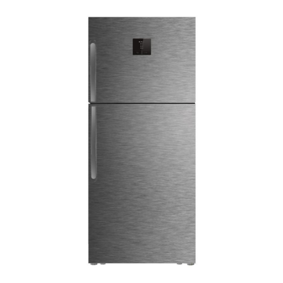
Page 3: Product Introduction
1.Product introduction Product front Front opening Product front Front opening Remarks :The diagram above shows two of these products. -
Page 4: Exploded View Of Product Structure
2. Exploded View of Product Structure 2.1 Exploded view of TRF-545W hidden handle refrigerator... - Page 5 Exploded view details of TRF-545W hidden handle refrigerator Serial Quantity used per English name Remark number unit The refrigerating chamber door seal Freezer foaming door body Handle Torsional spring For the water dispenser products Panel assembly lamp cover...
- Page 6 Exploded view details of TRF-545W hidden handle refrigerator Serial Quantity used English name Remark number per unit Return air cover assembly middle higne Lighting fixtures upper higne Upper hinge assembly Main Board main controller mounting cover ...
- Page 7 Exploded View of Product Structure 2.2 Exploded view of TRF-545W external handle refrigerator...
- Page 8 Exploded view details of TRF-545W external handle refrigerator Quantity Serial English name used per Remark number unit The refrigerating chamber door seal Freezer foaming door body Handle components Handle components Handle Torsional spring For the water dispenser products...
- Page 9 Exploded view details of TRF-545W external handle refrigerator Quantity used Serial number English name Remark per unit evaporator component Door lock holder optional For the products Display Board Component of the display in the refrigerating room Return air cover assembly ...
-
Page 10: Product Operation Rules
3. Product operation rules The TRF-545W series has two different displays , one on the door and one in a freezer. the display on the door IPowered on for the first time When the refrigerator is powered on for the first time, refrigerating chamber shall run when the temperature of refrigerating chamber and freezer chamber is set as 5℃... - Page 11 Regulation of the temperature of freezer chamber In the unlocking state, press and hold the “temperature regulation” key for 3 seconds, after the icon of the temperature zone is switched to that of the freezer chamber, press the “temperature regulation” key to regulate the temperature of the freezer. Then press the “temperature regulation”...
- Page 12 Child lock In the unlocking state, enter the “child lock” function: automatic startup: there is no key for this operation on the display panel, 30 seconds later, the child lock function will be automatically started, the “child lock” icon will be on, and the keyboard locked; exit the child lock: when the “child lock”...
- Page 13 3.2 the display in the refrigerating room First time to electricity For the initial power on, the refrigerator should operate in accordance with the middle 2 for the freezing chamber and middle 2 for the chilling chamber. The function of adjusting the temperature manually. Temperature adjustment in cooling room Repeatedly press the button of "...
- Page 14 Quick freezing function Under the status with the indictor at the temperature zone of freezing being on, repeatedly press the button of "Temp" until the "power freeze" function indicator is on, and then enter the quick-freezing function for the freezing chamber. After the refrigerator enters the "power freeze", it will enter the status of strong cooling, and will automatically exit after 4 hours.
-
Page 15: Refrigeration System And Electrical Control
4. Refrigeration system and electrical control Condenser Dew-proof tube Dry filter Capillary tube Finned-type evaporator Evaporation coil Compressor... - Page 16 Schematic diagram of freezer chamber Evaporator outlet, Evaporator inlet, connection pipe connection pipe for air return pipe for capillary tubes Evaporator must be exposed Reservoir while welding Lokring rings The fixed position of Defroster sensor Heating tube of Water tray is defroster coated with aluminum foil...
- Page 17 Schematic diagram of welding the pipeline for compressor chamber Connection of dew Connection of Connection of removable tube return pipe outlet evaporation coil and dry filter(steel and return outlet and condenser and copper) transition pipe inlet (steel and steel) (copper and copper) Connection between condenser...
- Page 18 Diagram of compressor wiring The wiring mode of two devices Electrical wiring diagram...
- Page 19 Electrical Control Circuit Diagram Some products do not have this circuit The diagram above is for reference only.please refer to the object.
- Page 20 Control of components: (1) Compressor If the refrigerator has refrigeration request, turn on the compressor; If the refrigerator has no refrigeration request, turn off the compressor; The shutdown time must be more than 8 minutes before it can be started again; (2) Light Turn on the switch of the refrigerating chamber door and turn on the refrigerating floodlight;...
- Page 21 (4) Damper During the refrigeration of refrigerating chamber, the damper is opened; When the refrigeration stops, the damper is closed (5) Air swing motor When the temperature of the refrigerating chamber is high, the air swing motor is turned on, and it is controlled that the start-up time last 10 minutes every 5-minutes shutdown;...
-
Page 22: Instructions For Disassembly Of Components And Parts
5.Instructions for Disassembly of Components and Parts 1) Disassembly of display panel: 1. Wear anti-static gloves and pull out the display panel with a suction cup. 2. Then remove the connecting terminal and replace it. 3. Install it in reverse order during assembly. - Page 23 2) Disassembly of refrigerator floodlight and freezer floodlight 1) pry the lamp cover up and remove it from the largest fitting clearance between the lamp cover and the cabinet liner with a 0.5mm steel ruler or similar flat tool (preferably the inner side of the assembly shown in the figure, even if the disassembly damage occurs in the area, it is hardly visible).
- Page 24 3) Disassembly of refrigerator air duct cover plate: 1. First, use a flat screwdriver to pry open the cover of screw hole, and then use a cross screwdriver to dismantle the screw; 2. Pull out the connector of air duct cover with hands and take out the air duct assembly and remove the duct foam with hands.
- Page 25 4) Disassembly of freezer air duct cover plate: First, use a flat screwdriver to pry open the cover of screw hole, and then use a cross screwdriver to remove the screw; Pull out the connector of air duct cover plate by hand; Use the cross screwdriver to remove the two screws of the hood and the two screws below the air duct, take down the hood and separate the upper and lower parts of the foam assembly;...
- Page 26 5) Instructions for Disassembly of Parts Disassembly of water dispenser display panel: First, use a straight line or other tools to reach the panel. It is best to wear anti-static gloves in your hands. Use the other end to gently push up the other end. Wait until the buckle is loose. Drag your hands up and wait for the buckle to loose That is, the two buckles above and the bottom two buckles are all detached, the panel can be disassembled, the disassembly process can not be too strong, too much force to remove the buckle is easy to break.
- Page 27 6) Disassembly of master control board: 1. Use a cross screwdriver to remove the screws of air duct assembly and remove the master control board cover; 2. Wear anti-static gloves, unplug the connector by hand, take out the master control board and replace it; 3.
- Page 28 7) Disassembly of hinge cover and door body: 1. Remove the screws of hinge cover with a cross screwdriver, then remove the hinge cover and replace the door lamp switch; 2. Remove the bolts of hinge cover with a M6 sleeve and remove the top hinge; 3.
- Page 29 8) Disassembly of compressor assembly: 1. Use a cross screwdriver to remove the screws of compressor cover plate 2. Place the compressor assembly on the workbench, remove the fixing screw with a spanner, and remove the remaining 4 screws in turn; 3.
- Page 30 9) Disassembly of starter/protector: 1. Place the compressor flat on the workbench and use a screwdriver to pry off the protective cover; 2. Pull the starter/protector out by hand; 3. Use a slotted screwdriver to separate the terminal from the plug to replace the starter/protector.
- Page 31 6. Maintenance guide Before maintenance, it is necessary to know the actual usage of the user before taking corresponding measures User usage Guidance and handling Surrounding clearance: more than 10 cm at No clearance around the back and more than 30 cm at the top, keep it ventilated.
- Page 32 6.1 Failure of electric control program Access to maintenance In case of unlocking, press and hold the “temperature regulation” key, and then press the “function” key for more than 5 seconds to enter the Access method maintenance procedure; Check the current temperature of each chamber temperature sensor; Check the current operating status of each load of the refrigerator;...
- Page 33 Fault code prompt and maintenance plan: Fault Fault Cause of failure Handling method display Check whether there is open circuit or short circuit Freezing sensor; open circuit Abnormal freezing sensor between the output end of the master control board or short circuit and the freezing sensor.
- Page 34 The compressor does not work: Whether the refrigerating Whether the power plug is Whether the voltage is normal chamber light is on plugged in Make the voltage stable and normal Plug in the power plug Whether the compressor works Check whether the master Replace the master control board control board is normal Use a multimeter to test whether...
- Page 35 Excessive noise: Excessive noise Whether the ground is flat Keep the ground level Resonance with objects through collision Avoid collision with objects Whether the pipelines in the compressor Adjust the pipeline to avoid collision compartment collide with each other...
- Page 36 The compressor does not stop for a long time: The compressor does not stop for a long time Move it to a place with low ambient Whether the ambient temperature temperature is too high Whether the door of the Close the door of the refrigerator refrigerator is closed tightly tightly Whether the gear is appropriate...
Need help?
Do you have a question about the TRF-545W and is the answer not in the manual?
Questions and answers