Table of Contents
Advertisement
Quick Links
Advertisement
Table of Contents

Related Manuals for Kobold DRS Series


Summary of Contents for Kobold DRS Series
- Page 1 Operating Instruction Turbine-wheel Flow Meter Model: DRS...
-
Page 2: Table Of Contents
Order Codes ....................12 Dimensions ....................13 EU Declaration of Conformance ..............15 Manufactured and sold by: Kobold Messring GmbH Nordring 22-24 D-65719 Hofheim Tel.: +49(0)6192-2990 Fax: +49(0)6192-23398 E-Mail: info.de@kobold.com Internet: www.kobold.com Page 2 DRS K06/0418... -
Page 3: Note
2. Note Please read and take note of these operating instructions before unpacking and putting the unit in operation and follow the instructions precisely as described herein. The devices are only to be used, maintained and serviced by persons familiar with these operating instructions and with the prevailing regulation applying to procedural safety and the prevention of accidents. -
Page 4: Operating Principle
5. Operating Principle The DRS flow meter operates on the turbine wheel principle. The liquid first flows through a laminar flow element that eliminates turbulence and routes the flow stream into the turbine wheel. The turbine wheel then starts to rotate. This rotary motion is sensed non-contacting by magnets embedded in the turbine wheel and converted to a frequency signal. -
Page 5: Electrical Connection
7. Electrical Connection 7.1. General Attention! Ensure that the power ratings of your supply system are in agreement with the power ratings of the flow meter. Please ensure that the electric supply lines are not active. Wire the connection cable/plug with the supply line according to the following connection diagram. - Page 6 7.3. Evaluation electronics: Frequency output and analogue output with Pt100 (DRS-..P) Plug connection (..F300P; Cable connection (..F500P; ..F320P, ..F340P, ..F390P, ..F520P, ..F540P, F590P) ..L303P; ..L343P) brown: +Vs blue: GND / Pt100 black: Signal white: PT100 2-wire grey: PT100 2-wire 7.4. Evaluation electronics: analogue output (..L..) 3-conductor (..L303, ..L343) n.c.
- Page 7 2-conductor (..L342) n.c. n.c. 2-conductor, DIN-plug (DRS-...L442) n.c. 7.5. Compact electronics: (..C30R, ..C30M, ..C34P, ..C34N) Please see Operating Instruction Manual for compact electronics with frequency output DRS K06/0418 Page 7...
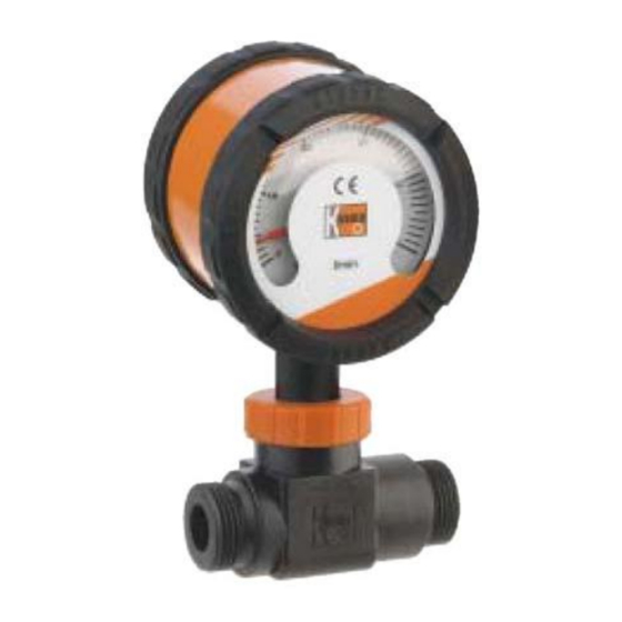
- Page 8 7.6. Evaluation electronics: Pointer display (..Z300, ..Z340) n.c. Signal Caution! In case current output is not needed, PIN 4 (Signal OUT) is to be permanently connected wit Ground (GND) (short circuit jumper). page 8 DRS K05/1116...
-
Page 9: Commissioning
8. Commissioning 8.1. Frequency output The measuring units are pre-adjusted and ready for operation after electrical connection. 8.2. Analogue output The measuring units are pre-adjusted and ready for operation after electrical connection. 8.3. Pointer display (..Z300, ..Z340) The measuring units are pre-adjusted and ready for operation after electrical connection. -
Page 10: Technical Information
10. Technical information 10.1. Sensor data Measuring range: 2-40 L/min water Sensor pulse output: 384 Hz at 40 L/min Metal Sensor (DRS-...150; DRS-...250) 352 Hz at 40 L/min plastic sensor (DRS-...350) Max. operating pressure: 200 bar (DRS-...150; DRS-...250) 16 bar (DRS- ...350) Temperature: -20 to +80 °C (medium, standard), -20...+150 °C (medium, -S00x), -20 to +100 °C (storage) - Page 11 DRS-...F390 Supply: 24 V ± 20 % Power consumption: 15 mA Pulse output: PNP, open collector, max. 20 mA Frequency divider: 1...1/128, factory setting Option: Pt 100, 2-wire Response time (Pt100): = 100 s DRS-...L... Supply: 24 V ± 20% Output: 0(4)-20 mA, 3-wire or 2-wire 500 ...
-
Page 12: Order Codes
11. Order Codes Order Details (example: DRS-9350 I4 L303 0) Material Model Connection Evaluating electronics Option sensor housing Frequency output F300 = Plug connector M12x1, PNP F320 = Plug connector M12x1, PNP, divider 1:2 F340 = Plug connector M12x1, PNP, divider 1:4 F390 = Plug connector M12x1, PNP, divider 1... -
Page 13: Dimensions
12. Dimensions Connection threads: female/female; male/male and female/male with the same outer dimensions. Kabel- version M12x1 SW 32 DRS-...F/...L DRS K06/0418 Page 13... - Page 14 44,5 13,5 Cable 2 m with plug M 12x1 SW 36 OBOLD SW 32 DRS-...C DRS-...Z D = Sealing areas page 14 DRS K05/1116...
-
Page 15: Eu Declaration Of Conformance
13. EU Declaration of Conformance We, KOBOLD-Messring GmbH, Hofheim-Ts, Germany, declare under our sole responsibility that the product: Turbine-wheel Flow Meter Model: DRS to which this declaration relates is in conformity with the standards noted below: EN 61000-6-4:2011 Electromagnetic compatibility (EMC) - Part 6-4: Generic standards - Emission...
Need help?
Do you have a question about the DRS Series and is the answer not in the manual?
Questions and answers