Advertisement
Quick Links
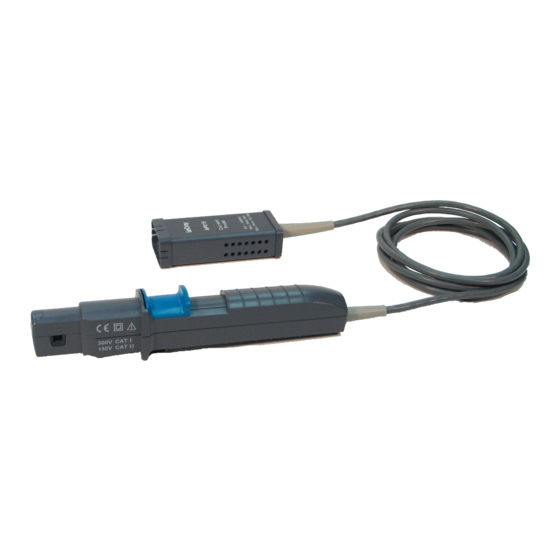
AP015 Current Probe
Specifications
The following specifications are valid for model AP015 current probes after the probe has reached operating
temperature, which is 20 minutes with power applied in a environment with stable ambient temperature. The
probe must be operating within the environmental conditions listed in the General Characteristics section, and
has been calibrated within the past 12 months in a ambient temperature of 23 ±5
Nominal Characteristics
Nominal characteristics describe parameters and attributes which are guaranteed by design, but do not have
associated tolerances.
INTERFACE:
COUPLING:
MAXIMUM CURRENT, DC±30A (CONTINUOUS)
±50A MAXIMUM (<10S)
SENSITIVITY:
10 MA/DIV – 20 A/DIV
OFFSET RANGE
±100A MAXIMUM
MAXIMUM CONDUCTOR SIZE
MAXIMUM VOLTAGE, BARE CONDUCTOR
CABLE LENGTH
WEIGHT, PROBE ONLY300 G (10.6 OZ.)
Warranted Electrical Characteristics
Warranted characteristics describe parameters which have guaranteed performance. Unless otherwise noted,
tests are provided in the Performance Verification Procedure for all warranted specifications.
DC ACCURACY:±1% OF READING TO 15A (AT 25
±2% OF READING TO 30A (AT 25
BANDWIDTH
Typical Electrical Characteristics
Typical characteristics describe parameters which do not have guaranteed performance, however are
representative of the average performance from a sample of several probes. Tests for typical characteristics
are not provided in the Performance Verification Procedure.
WOE-CS-TS02-009v002
PROBUS
AC, GND, DC
5 MM
300 V CAT I
150 V CAT II
2 M
C, AFTER DEGAUSS)
O
C, AFTER DEGAUSS)
O
DC TO 50MHZ
1/111
Instruction Manual
o
C.
Advertisement

Related Manuals for PEWA AP015


Summary of Contents for PEWA AP015
- Page 1 Instruction Manual Specifications The following specifications are valid for model AP015 current probes after the probe has reached operating temperature, which is 20 minutes with power applied in a environment with stable ambient temperature. The probe must be operating within the environmental conditions listed in the General Characteristics section, and has been calibrated within the past 12 months in a ambient temperature of 23 ±5...
- Page 2 AP015 Current Probe Instruction Manual RISE TIME: < 7 NS SLEW RATE> 1.6 A/NS ( SENSITIVITY ≥ 1 A/DIV) INSERTION IMPEDANCE< 0.06Ω AT 5 MHZ General Characteristics TEMPERATURE: 0 – 40 C OPERATING RELATIVE HUMIDITY80% MAXIMUM UP TO 31 USAGE ENVIRONMENT...
- Page 3 BNC female to banana plug. Pomona 1269 Patch Cables Male Banana – Male Banana, 12” Pomona B-12-0 (black) (4 reequired) B-12-2 (red) Preliminary Procedure Connect the AP015 to the channel 1 input of the oscilloscope, and completely close the probe slider. WOE-CS-TS02-009v002 3/111...
- Page 4 AP015 Current Probe Instruction Manual Turn the oscilloscope on and allow at least 30 minutes warm-up time for the AP015 and test equipment before performing the Verification Procedure. Turn on the other test equipment and allow these to warm up for the time recommended by the manufacturer.
-
Page 5: Check Bandwidth
CF02, using the matched BNC coaxial cable specified for use with the leveled sine wave generator. Open the slider and connect the AP015 to the high speed shunt calibration fixture. Close and lock the probe slider by pushing it fully away from the probe cable. - Page 6 (located on the coupling menu), twice. DEGAUSS Open the AP015 slider and position the probe input around the 50 Turn loop. Close and LOCK the slider. Set the oscilloscope channel vertical scale to 20A/div.
- Page 7 10 seconds before shutting the current off. Record '>10sec' on the test record. This completes the Performance Verification of the AP015. Complete and file the results recorded in the AP015 Performance Verification Test Record as required by your quality procedures.
- Page 8 A D J U S T M E N T P R O C E D U R E Introduction This procedure can be used to adjust the AP015 Current Probe in order to meet the warranted gain specification. The other parameters verified in the Performance Verification procedure do not have adjustments associated with them.
- Page 9 AP015 Current Probe Instruction Manual Procedure A. Adjust R24, Gain With the AP015 Current Probe removed from any signal and the slider returned to the LOCKED position, degauss the probe by pressing the button, (located on the coupling menu), twice. DEGAUSS Connect the AP015 to the 50 Turn loop, and set the oscilloscope vertical scale to 20A/div.
- Page 10 AP015 Current Probe Instruction Manual A P 0 1 5 P E R F O R M A N C E V E R I F I C A T I O N T E S T R E C O R D This record can be used to record the results of measurements made during the performance verification of the AP015 Current Probe.
- Page 11 AP015 Current Probe Instruction Manual A P 0 1 5 P E R F O R M A N C E V E R I F I C A T I O N T E S T R E C O R D...
Need help?
Do you have a question about the AP015 and is the answer not in the manual?
Questions and answers