
Related Manuals for PEWA Megger TDR1000/3


Summary of Contents for PEWA Megger TDR1000/3
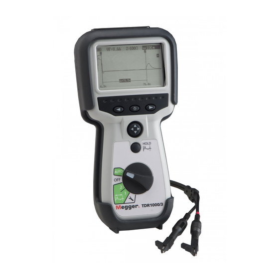
- Page 1 TDR1000/3 TDR1000/3P CFL510G TDR500/3 Time Domain Reflectometers User Manual Page 1 of 1...
-
Page 2: Table Of Contents
CONTENTS Introduction ...........................................5 Overview..........................................7 Instrument layout and display ..................................7 Controls...........................................9 Rotary switch........................................9 Range and cursor control .....................................10 Backlight and hold......................................11 Setup ..........................................12 Operation..........................................13 General testing procedure ....................................13 Operating modes ......................................13 Connection to cable under test ...................................14 Velocity factor........................................16 Pulse widths........................................17 Techniques..........................................18 Test the cable from both ends..................................18 Care and maintenance......................................18... - Page 3 SAFETY WARNINGS ■ Safety warnings and precautions must be read and understood before the instrument is used. All Safety warnings and precautions must be observed during use. ■ The circuit under test must be switched off, de-energised, securely isolated and proved safe before test connections are made.
- Page 4 Symbols The following symbols are used on this instrument CAUTION: RISK OF DANGER EQUIPMENT PROTECTED THROUGHOUT BY DOUBLE INSULATION OR REINFORCED INSULATION EQUIPMENT COMPLIES WITH RELEVANT EU DIRECTIVES EQUIPMENT COMPLIES WITH AUSTRALIAN EMC REQUIREMENTS (C-tick) (NOT FOR SAFETY) THIS EQUIPMENT SHOULD BE RECYCLED AS ELECTRONIC WASTE Page 4 of 4...
-
Page 5: Introduction
Introduction Thank you for purchasing this cable fault locator. Before attempting use of your new instrument please take the time to read this user guide, ultimately this will save you time, advise you of any precautions you need to take and could prevent damage to yourself and the instrument. - Page 6 The instrument can be used on any cable consisting of at least two separate conductive elements, one of which may be the armouring or screen of the cable. It has internal matching networks to allow testing of 25 Ω, 50 Ω, 75 Ω and 100 Ω cables. (These typically correspond to power, coaxial data and data/telecoms cable).
-
Page 7: Overview
Overview Instrument Layout & Display Left & Right Arrows used in setup Backlit 256 x 128 dot matrix display Backlight Four Way Joy Switch Mainly controls range and cursor There is an audible tone on key presses. A low tone means the key Hold key is invalid Rotary Switch... - Page 8 Velocity Impedance Display Factor Range Battery State Cursor 2 Indication Cursor 1 Hold Indicator Cursor 2 Position Cursor 1 Distance Between Position Cursor 1 & 2 Page 8 of 8...
-
Page 9: Controls
Controls Rotary Switch Turn the switch from OFF to another position to turn the instrument on. The instrument may be turned off, by switching to OFF, or the instrument may switch itself off if it has not been used for 5 minutes or the battery is exhausted. The other selections are Auto *Cursor 2... -
Page 10: Range And Cursor Control
Range & Cursor Control The range is set using the four way switch; press up to Moving the four-way switch left or right will move the active increase the range and down to reduce the range. cursor. Page 10 of 10... -
Page 11: Backlight And Hold
Backlight & Hold Backlight key. Press the backlight key to switch the backlight Hold key. When the rotary switch is set to cursor 1, cursor 2, or on. It will switch off after one minute with no key press Auto, pressing the hold key will place an image of the current when activated, or it may be switched off by pressing the key trace in grey on the display. -
Page 12: Setup
Setup The setup position allows the Velocity Factor, Impedance, Pulse Width, Gain, Distance Units, Sound and Display Contrast to be set. These are remembered when the instrument is switched off and recalled when switched back on. To adjust any of these parameters turn the rotary switch to the setup position. The parameter to be adjusted is highlighted at the top of the screen. -
Page 13: Operation
Operation General Testing procedure Ensure the correct test leads are firmly fitted into the sockets of the instrument. Switch on the instrument. The instrument will display the start screen for a couple of seconds, followed by a trace. The instrument will remember the settings last used. If necessary, adjust the display contrast and distance units to the preferred settings. -
Page 14: Connection To Cable Under Test
Connection to Cable Under Test Connect the test lead to the cable under test. Connection may be made to a live power system with a voltage to earth (ground) less than 150 V with an installation (over voltage) category of I V or lower. This means that the instrument may be connected to any to primary supply circuits such as overhead cables. - Page 15 The 4mm plug to BNC adapter accessory is for use on cable distribution systems and low voltage cables only. The operator must verify that the circuit is safe for testing and take the appropriate precautions. In the event of no reflections being visible, increase gain in setup mode until any reflection can be easily identified. (If no reflections can be seen, try shorting or earthing the far end of the cable to ensure that you are “seeing”...
-
Page 16: Velocity Factor
Velocity Factor The velocity factor is used by the instrument to convert the measured time for a pulse to be reflected, into a distance. It is displayed as a ratio of the speed of light (eg 0.66 = 66% of the speed of light). If the exact length of cable is known and the reflection from the cable end is visible then an accurate velocity factor can be determined: Locate the reflection caused by the end of the known length of cable with the instrument set on the shortest possible... -
Page 17: Pulse Widths
Pulse Widths As the range of the TDR is adjusted so the duration of the transmitted pulse changes. The pulse width range varies from 2 ns to overcome signal attenuation and enable the instrument to see further down a length of cable. The greater the range selected on the TDR, the wider the transmitted pulse. -
Page 18: Techniques
Techniques To improve on the accuracy of the measurement, numerous techniques can be used, depending on the situation encountered. Not every situation can be described, but the following points are effective and the most common and easily implemented methods. Test the cable from both ends When fault finding on a cable it is good practice to take measurements from both ends, particularly in the case of open circuit faults, when the true end of the cable is not visible. -
Page 19: Battery
Battery Battery Replacement Switch off the instrument Disconnect the instrument from any electrical circuits 2 - Undo Screws x 2 Undo two screws 1 - Disconnect Remove the battery cover from Leads the base. For battery replacement: Remove old batteries Refit new batteries following correct polarity as marked on the battery holder... -
Page 20: Battery Indicator
Battery type: 5 x 1.5 V Alkaline LR6 (AA) or NiMH HR6 rechargeable. The crossed out wheeled bin placed on the batteries is a reminder not to dispose of them with general waste at the end of their life. Alkaline and NiMH batteries are classified as portable batteries and must be disposed of in accordance with local regulations. -
Page 21: Specifications
Specifications Except where otherwise stated, this specification applies at an ambient temperature of 20 ºC General Ranges: 10 m 25 m 100 m 250 m 1000 m 2500 m 5000 m 30 ft 75 ft 300 ft 750 ft 3000 ft 7500 ft 15000 ft Accuracy: ±1% of range ±... - Page 22 Safety When using the Fused Test Lead Set this instrument complies with EN 61010-1 for connection to live systems with less than 300V between the terminals and 150V CATIV to earth. When using the Miniature clip Test Lead Set, Bed of Nails Test Lead Set or BNC Adapter the system is rated for safety low voltage systems only.
-
Page 23: Waste Electrical And Electronic Equipment
Waste electrical and electronic equipment WEEE The crossed out wheeled bin placed on Megger products is a reminder not to dispose of the product at the end of its life with general waste. Megger is registered in the UK as a producer of electrical and electronic equipment. The Registration Number is WEE/HE0146QT. - Page 24 Ordering Information Item Order No. TDR1000/3 Time Domain Reflectometer 1001-788 includes Miniature clip test lead set TDR1000/3P Time Domain Reflectometer 1001-789 includes fused test lead set CFL510G Time Domain Reflectometer 1001-790 includes Bed of Nails test lead set and BNC adapter Accessories User information CD 2002-178...
-
Page 25: Test Lead Selection
Test Lead selection Fused test lead set Megger Part Number 1001-717 must be used on power systems Other test leads and the BNC adapter must only be used on low voltage systems Page 25 of 25... -
Page 26: Repair And Warranty
Repair and Warranty The instrument contains static sensitive devices, and care must be taken in handling the printed circuit board. If an instrument’s protection has been impaired it should not be used, but sent for repair by suitably trained and qualified personnel. The protection is likely to be impaired if for example, it shows visible damage, fails to perform the intended measurements, has been subjected to prolonged storage under unfavourable conditions, or has been subjected to severe transport stresses. - Page 27 CALIBRATION, REPAIR AND SPARE PARTS For service requirements for Megger Instruments contact: Megger Limited Archcliffe Road Dover Kent CT17 9EN England. Tel: +44 (0) 1304 502 243 Fax: +44 (0) 1304 207 342 Megger operate fully traceable calibration and repair facilities, ensuring your instrument continues to provide the high standard of performance and workmanship you expect.
- Page 28 Returning your product to Megger - UK and USA service centres When an instrument requires calibration, or in the event of a repair being necessary, a Returns Authorisation (RA) number must first be obtained from one of the addresses shown on the following page. You will be asked to provide the following information to enable the Service Department to prepare in advance for receipt of your instrument, and to provide the best possible service to you.
Need help?
Do you have a question about the Megger TDR1000/3 and is the answer not in the manual?
Questions and answers