Advertisement
Quick Links
Operating Manual
S0080
50 Event 24 Hour 7 day Timer - Din Rail
1.0 OVERVIEW
The A S0080 is a 7 day timer housed in a convenient DIN rail housing, which has four closing contact outputs. It permits a
total of 50 station (event) switching times. Each can be set to turn on any single day of the week or on multiple days, from
1 sec up to 24 hours. Switching events programmed for multiple days count as only a single station (event) and each of
the 50 event times may be set to any (but not multiple) output.
Manual override is provided so that any of the four outputs can be set "ON" or "OFF" manually which overrides any of
the event times programmed for that output.
The unit has security lock out of Time Edit, Station Edit and Clear Memory Functions via DIP switch selection.
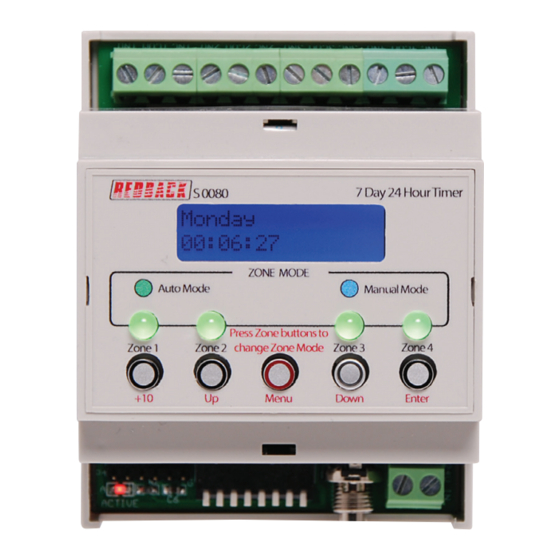
2.0 OPERATION
On the front of the timer there are four LED's and five switches which provide a visual indication of the status of each of
the four output zones and provide navigation of the programming menu (Refer to Fig 2.1).
The LED's indicate whether a zone is in "Auto" mode or "Manual' mode. A green LED indicates a zone is in "Auto" mode,
and will therefore follow the programmed sequence of triggers entered by the user.
A blue LED indicates that a zone is in "Manual" mode and therefore has been manually set to be either "ON" or "OFF" by
the user. Once a zone is in "Manual" mode it will stay in this mode until the user sets it back to "Auto" mode, or the unit
is switched off (NOTE : All zones will return to 'Auto Mode' on power up).
The switches are used to navigate the programming menu, while the switch LED's indicate the output status of the zone.
i.e. if the zone is "On" or "Off".
On the rear of the unit are the four, output zone "voltage free" closing contacts. Provision has been included for a normal-
ly open and a normally closed contact on each output.
If a zone is set to "ON" the corresponding output zone will become active. The normally open (N/O) contact for that zone
will short, the normally closed contact (N/C) will become open and these contacts will stay this way until the zone is again
set "OFF".
User manual revision number: 1.1 29/11/2022
Advertisement

Related Manuals for Redback S0080


Summary of Contents for Redback S0080
- Page 1 1.0 OVERVIEW The A S0080 is a 7 day timer housed in a convenient DIN rail housing, which has four closing contact outputs. It permits a total of 50 station (event) switching times. Each can be set to turn on any single day of the week or on multiple days, from 1 sec up to 24 hours.
- Page 2 Essentially this means that as soon as the Menu button is pressed the unit is no longer in “Auto Mode”. Make sure to return to the main screen by exiting all menu’s when not making changes. 3.0 CONNECTIONS Figure 3.1 shows the layout of the S0080. Output Closing Contacts OUTPUT 1 OUTPUT 3...
-
Page 3: Important Note
Switch 4 - Clear Memory Lockout When switch 4 is set to the “ON” access to the Clear Memory Mode will be restricted. Therefore there can be no erasing of the Station (Event) times stored in memory. Redback® Proudly Made In Australia... - Page 4 1 of the message player. With the addition of the Redback S 4455 10 amp relay box we can switch as external supply to power a high current drawing device. The S 4455 can be set to 12/24/48V operation (in this case we have set it to 24V) via the on board jump- er.
-
Page 5: Battery Backup
Inside you will find two boards which are screwed together. Carefully removed these from the DIN rail enclosure. Fig 4.1 Fig 4.2 The battery required is a 3V Lithium (CR2032) such as Redback S 4999B and is mounted in a vertical mount battery holder as shown in figures 5.1 and 5.2. Fig 4.3 Fig 4.4... -
Page 6: Navigating The Menus
3.1.1 Manual Selection OF Output Zones QUICK ACCES MANUAL OPERATION After selecting this option the screen should appear as shown in Fig 3.4. The square brackets indicate the cursor position on the screen. OUTPUT 1 Fig 3.4 [AUTO] Redback® Proudly Made In Australia... -
Page 7: Special Note
Navigate to the “Add or Edit a Station Time” Sub Menu as shown in Fig 3.3. If this is the first time entering this menu the screen should appear as shown in Fig 3.6. The number “1)” shown is the Station (or Event) number which is highlighted by a flashing cursor. Fig 3.6 Start @ 00:00:00 Redback® Proudly Made In Australia... - Page 8 Once the day or multiple days desired is shown on the LCD, press the “Enter” button to confirm. The cursor will now move to the start time. This is the time the “Event” is to take place and is in 24 hour format. Redback® Proudly Made In Australia...
- Page 9 Press the UP and DOWN 3) ZONE DURATION buttons to scroll up and 00:00:00 down. Enter Press the ENTER button to make your selection Menu Press the MENU button to exit at any time. 49) ZONE DURATION 00:00:00 Redback® Proudly Made In Australia...
- Page 10 Press the UP and DOWN 02:00:00 buttons to change the Duration” screen. hour/min/secs. Enter Press the ENTER button to make your selection Menu Press the MENU button to exit at any 1) ZONE DURATION time. 22:00:00 Fig 3.13 Redback® Proudly Made In Australia...
- Page 11 If you press Enter, the unit will cycle through the memory locations clearing any data stored. This will take a few minutes. Once finished you will return back to the Clear Memory Sub Menu. NOTE: It is advisable to now set DIP switch 4 to “ON” to prevent accidental clearing of the memory. Redback® Proudly Made In Australia 11...
- Page 12 A sheet has been provided to record all of the Event(s) information for easy reference. OUTPUT 1 = OUTPUT 2 = OUTPUT 3 = OUTPUT 4 = STATION OUTPUT TURN ON TIME DURATION TURN OFF TIME Redback® Proudly Made In Australia...
Need help?
Do you have a question about the S0080 and is the answer not in the manual?
Questions and answers