Table of Contents
Advertisement
Quick Links
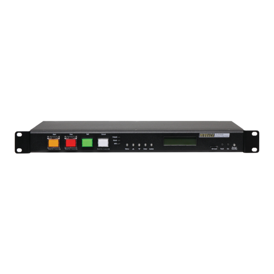
Redback® A 4500C Evacuation Timer with Network Access
A 2078B Remote Plate
A 4578 Remote Plate
Please read these instructions carefully from front to back prior to installation.
Failure to follow these instructions may prevent the unit from working as designed.
www.redbackaudio.com.au
These instructions are only suitable for A 4500C models or A 4500B
models which have been upgraded with the A 4500C firmware.
Firmware updates are available from
A 4500C
Alert/Evacuation Controller and 50 Event Timer
A 2078B
Alert/Evac/Cancel Remote Wall Plate (Hard Wired)
A 2081
Alert/Evac/Chime/Cancel Remote Wall Plate (Hard Wired)
A 4578
Alert/Evac/Cancel Remote Wall Plate (U/UTP Cat5)
A 4579
A 4581
Alert/Evac/Chime/Cancel Remote Wall Pl
A 4581V
Alert/Evac/Chime/Cancel Remote Wall Pl
A 4564
Emergency Paging Microphone Console (U/UTP Cat5)
A 2081 Remote Plate
A 4581 Remote Plate
IMPORTANT NOTE:
They include important setup instructions.
IMPORTANT NOTE:
Operating Manual
Timer Isolate Remote Wall Plate (U/UTP Cat5)
A 4579 Remote Plate
A 4581V Remote Plate
User manual revision number: 1.1 04/08/2022
Redback® Proudly Made In Australia
redbackaudio.com.au
Optional Accessories
ate
(U/UTP Cat5)
ate
(U/UTP Cat5)
A 4564 Paging Console
1
Advertisement
Table of Contents

Related Manuals for Redback A 4500C


Summary of Contents for Redback A 4500C
- Page 1 Redback® A 4500C Evacuation Timer with Network Access IMPORTANT NOTE: These instructions are only suitable for A 4500C models or A 4500B models which have been upgraded with the A 4500C firmware. redbackaudio.com.au Firmware updates are available from Operating Manual...
- Page 2 - no recorded messages, call centres or automated push button options. It’s not only the assembly team at Redback who are employed as a direct result of your purchase, but hundreds more at local companies used in the supply chain.
-
Page 3: Table Of Contents
Redback® A 4500C Evacuation Timer with Network Access CONTENTS 1.0 Overview Page 1.1 Introduction 1.2 Features 1.3 What’s in the box 1.4 Front panel guide 1.5 Rear panel connections 2.0 Setup 2.1 Initial Setup 2.2 Alert, Evac and Bell Switches 2.3 Setting the current time... -
Page 4: Introduction
1.1 INTRODUCTION The A 4500C is a weekly timer and Evacuation controller all housed in a convenient 1RU rack mount chassis. A total of 50 “event” switching times are available through the timing functions. Each event can be set to turn on any single day of the week or on multiple days, from 1 sec up to 24 hours. -
Page 5: Front Panel Guide
Redback® A 4500C Evacuation Timer with Network Access 1.4 FRONT PANEL GUIDE Figure 1.4 shows the layout of the A 4500C front panel. 9 10 11 Alert Evac Bell Cancel A 4500 A 4500C 24 Hour 7 Day Timer 24 Hour 7 Day Timer... -
Page 6: Rear Panel Connections
“Normal” or “Failsafe” modes (see section 2.12 for more details). Network Adapter This RJ45 port is for connection of a Redback® proprietry adaptor board. This allows connection to an ethernet network. The Redback A 4498 Network connection pack is required (see section 3.0 for details). - Page 7 Redback® A 4500C Evacuation Timer with Network Access Audio Out RCA Connectors Connect these outputs to the input of the background music amplifier. Bell Contact These contacts are for remote triggering of the Bell tone. These could be triggered by a remote switch or other closing contact.
-
Page 8: Initial Setup
Out of the box the A 4500C comes supplied with default audio files installed for the Alert, Evac, Bell, Prebell, Music and Voice Over functions. If these files are missing or corrupt the unit will not continue. All of this information is stored on the Micro SD card. - Page 9 Redback® A 4500C Evacuation Timer with Network Access ress the “Menu” button on the front of the timer. The unit is now in “Menu Mode” and the screen should display the “Clock Adjust” Screen. This is the first of seven sub menu screens which are navigated by pressing the up and down buttons as shown in Fig 2.3b.
-
Page 10: Programming The Timing Events Using The Supplied Pc Software
Fig 2.5a The top left text is the time event number. Up to 50 events can be programmed into the A 4500C. Pressing the “up” and “down” buttons at this stage will move up and down through the events 1- 50. The top right text indicates that TIME1 (Event1) is currently disabled. -
Page 11: Deleting A Programmed Time
Once the days of the week are set, press the enter button to confirm and be returned to the main menu. Repeat this process for any other events to be programmed. This process of entering the events can be quite time consuming so it is recommended using the PC software (Redback Weekly Timer Programmer.exe). -
Page 12: Ev Chanegover
Redback® A 4500C Evacuation Timer with Network Access Press the “UP” button to reset all the times programmed and stored on the Micro SD card. Press the “No” button to exit without resetting the times. 2.8 EV CHANGEOVER Select the “EV CHANGEOVER” option from the menu (refer to figure 2.3b). -
Page 13: Dip Switch Settings
The output levels of the Alert/Evac, Prebell, Bell, Music and Voice Over tones can all be adjusted via trimpots located on the rear of the unit. 2.12 DIP SWITCH SETTINGS The A 4500C has various options which are set by the DIP switches on the rear of the unit. These are outlined below in figure 2.11. IMPORTANT NOTE: Ensure power is switched off when adjusting DIP switches. -
Page 14: Network Access
3.0 NETWORK ACCESS The Redback® A 4500C has been upgraded from previous versions to now include access via a network connection. The unit is connected with the addition of the Redback® A 4498 Network Connection Pack. With the upgraded PC software all the event timing and audio file selection can be adjusted remotely. -
Page 15: Remote Wall Plates
While the A 2081 wall plate provides a remote means of triggering the Alert, Evacuation and Bell tones and the cancel function. Connection from the A 2078B is made to the A 4500C via a minimum of 6 wires as shown in Fig 4.1A. Connec- tion is made from the A 2081 to the A 4500C via a minimum of 8 wires as shown in Fig 4.1B. - Page 16 A 2081 REMOTE WALL PLATE - + - + Cancel Chime Evac Alert Chime Evac Alert Switch Switch Switch Switch Lamp Lamp Lamp Fig 4.1B Connecting the A 2081 Wall Plate to the A 4500C www.redbackaudio.com.au Redback® Proudly Made In Australia...
-
Page 17: A 4578, A 4579, A 4581 An A 4581V Remote Plates
“flip up” covers to prevent accidental operation. Connection is made to the A 4500C via standard Cat5e cabling as shown in Fig 3.2 There are two RJ45 ports on the rear of the wall plates, either of which can be used. Only one A 4578, A 4579, A 4581 or A 4581V wall plate is allowed to be connected to the A 4500C via the “To Wall Plate”... -
Page 18: Paging Console
Provision has been made for the connection of one only paging console which is wired back to the A 4500C via CAT5E cabling to the RJ45 “To Paging Console” port on the rear of the A 4500C (see figure 4.1 for details). -
Page 19: Troubleshooting
Redback® A 4500C Evacuation Timer with Network Access 6.0 TROUBLE SHOOTING 6.1 SYMPTOMS AND REMEDIES SYMPTOMS REMEDIES PC SOFTWARE WILL NOT RUN The PC software for this product may not run on all PC’s. The .NET framework on the PC has to be updated to .NET Framework 4. -
Page 20: Firmware Update
6) With the power turned OFF, insert the Micro SD card back into the A 4500C. 7) Turn the A 4500C ON. The unit will check the Micro SD card and if an update is required the A 4500C will perform the update automatically.
Need help?
Do you have a question about the A 4500C and is the answer not in the manual?
Questions and answers