Table of Contents
Advertisement
Quick Links
Operating Manual
A 1708
50 Event 4 Output 24 Hour 7 day Timer
Redback® Proudly Made In Australia
IMPORTANT NOTE:
Please read these instructions carefully from front to back prior to installation.
They include important setup instructions.
Failure to follow these instructions may prevent the unit from working as designed.
User manual revision number: 1.0 13/05/2015
Advertisement
Table of Contents

Related Manuals for Redback A 1708


Summary of Contents for Redback A 1708
-
Page 1: Operating Manual
Operating Manual A 1708 50 Event 4 Output 24 Hour 7 day Timer Redback® Proudly Made In Australia IMPORTANT NOTE: Please read these instructions carefully from front to back prior to installation. They include important setup instructions. Failure to follow these instructions may prevent the unit from working as designed. -
Page 2: Operation
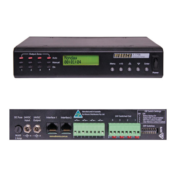
1.0 OVERVIEW The A 1708 is a versatile timer which has four switched 24V DC outputs and four closing contacts which activate simultaneously. It permits a total of 50 station (event) switching times. Each can be set to turn on any single day of the week or on multiple days, from 1 sec up to 24 hours. - Page 3 4) Clear Memory of ON/OFF Times 3.1.1 Manual Selection OF Output Zones After selecting this option the screen should appear as shown in Fig 3.4. The square brackets indicate the cursor position on the screen. OUTPUT 1 Fig 3.4 [AUTO] Redback® Proudly Made In Australia...
-
Page 4: Special Note
Navigate to the “Add or Edit a Station Time” Sub Menu as shown in Fig 3.3. If this is the first time entering this menu the screen should appear as shown in Fig 3.6. The number “1)” shown is the Station (or Event) number which is highlighted by a flashing cursor. Fig 3.6 Start @ 00:00:00 Redback® Proudly Made In Australia... - Page 5 Once the day or multiple days desired is shown on the LCD, press the “Enter” button to confirm. The cursor will now move to the start time. This is the time the “Event” is to take place and is in 24 hour format. Redback® Proudly Made In Australia...
- Page 6 Press the UP and DOWN 3) ZONE DURATION buttons to scroll up and 00:00:00 down. Enter Press the ENTER button to make your selection Menu Press the MENU button to exit at any time. 49) ZONE DURATION 00:00:00 Redback® Proudly Made In Australia...
- Page 7 Press the UP and DOWN 02:00:00 buttons to change the Duration” screen. hour/min/secs. Enter Press the ENTER button to make your selection Menu Press the MENU button to exit at any 1) ZONE DURATION time. 22:00:00 Fig 3.13 Redback® Proudly Made In Australia...
- Page 8 Press the UP and DOWN buttons to change the 02:00:00 Edit hour/min/secs. Enter Press the ENTER button to make your selection Menu Press the MENU button to exit at any Monday time. 22:00:00 Edit Fig 3.14 Redback® Proudly Made In Australia...
-
Page 9: Important Note
Ensure power is switched off when adjusting DIP switches. New settings will be effective when power is switched back on. There are four DIP switches accessible on the rear of the A 1708 which are for selecting the backup battery and various security lockout features (See Fig 4.1). -
Page 10: Battery Backup
Fig 6.1 6.2 DC Fuse The A 1708 is fitted with an M205 fuse holder with fuse rated at 2A. 6.3 Interface 1 and Interface 2 These are for future connection of product. Do not connect leads to these ports. - Page 11 A 1741MP3 Message player. Fig 6.5 demonstrates an example of how to connect the A 1708 to the A 1741. A 24V DC plugpack is used to power the A 1708, the 24V DC output of the timer is then fed into the A 1741 using a power lead with 2.1mm DC connectors such as the Altronics P 6717.
- Page 12 A sheet has been provided to record all of the Event(s) information for easy reference. OUTPUT 1 = OUTPUT 2 = OUTPUT 3 = OUTPUT 4 = STATION OUTPUT TURN ON TIME DURATION TURN OFF TIME Redback® Proudly Made In Australia...
Need help?
Do you have a question about the A 1708 and is the answer not in the manual?
Questions and answers