urmet domus sinthesl 1083/19 Quick Start Manual
Call module
Hide thumbs
Also See for sinthesl 1083/19:
- Manual (32 pages) ,
- Programming manual (36 pages) ,
- Manual (12 pages)
Table of Contents
Advertisement
PERFORMANCES ............................................................................2
DESCRIPTION OF TERMINALS .......................................................2
TECHNICAL CHARACTERISTICS ....................................................3
DEFAULT CONFIGURATION ...........................................................3
INSTALLATION .................................................................................3
Camera module connection .........................................................4
Product list ...................................................................................4
PROGRAMMING ..............................................................................4
Confi guration programming .........................................................4
Confi guration parameter ...............................................................4
Name programming ......................................................................6
Programming of door opener code ..............................................6
Audio adjusting .............................................................................6
Call to users ..................................................................................7
Call by entering physical code .....................................................7
Call by entering logical code ........................................................7
Call by selecting name from repertory .........................................7
Call to switchboard .......................................................................7
Communication and door opening ...............................................7
Transmission of special codes .....................................................8
Lock management ........................................................................8
Entry of door opener codes ..........................................................8
"Postman" function ......................................................................8
Programming via Bluetooth ..........................................................8
2 VOICE - Technical Manual
SECTION 3H
CALL MODULE
Download from www.urmet.com Technical Manuals area.
SECTION CONTENTS
2
TERMINAL PINS DESCRIPTION ......................................................9
INSTALLATION .................................................................................9
VIEWING ANGLES .........................................................................11
REPERTORY MODULE Ref. 1148/50
BLANK MODULE Ref. 1148/59
9
11
11
1
sec.3h −−−−
Advertisement
Table of Contents

Related Manuals for urmet domus sinthesl 1083/19


Summary of Contents for urmet domus sinthesl 1083/19
-
Page 1: Table Of Contents
SECTION 3H CALL MODULE Download from www.urmet.com Technical Manuals area. SECTION CONTENTS DIGITAL CALL MODULE CAMERA MODULE Ref. 1748/40 Ref.1083/19 (2 Modules) TERMINAL PINS DESCRIPTION ............9 PERFORMANCES ................2 INSTALLATION .................9 DESCRIPTION OF TERMINALS ............2 VIEWING ANGLES .................11 TECHNICAL CHARACTERISTICS ............3 DEFAULT CONFIGURATION ............3 REPERTORY MODULE Ref. -
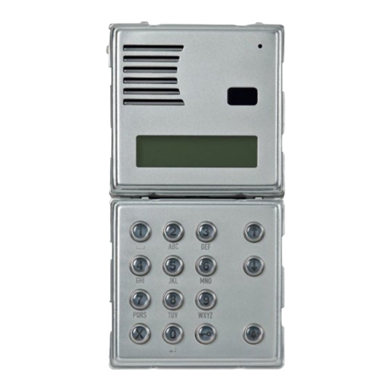
Page 2: Digital Call Module Ref.1083/19 (2 Modules)
DIGITAL CALL MODULE Ref.1083/19 (2 Modules) PERFORMANCES - STRUCTURE - DESCRIPTION OF TERMINALS DIGITAL CALL MODULE FRONT VIEW Ref.1083/19 (2 Modules) The call module Ref.1083/19 is dedicated to the 2Voice system made on a two-module Sinthesi structure. The new keypad has a new design and higher quality fi... -
Page 3: Technical Characteristics
DIGITAL CALL MODULE Ref.1083/19 (2 Modules) TECHNICAL CHARACTERISTICS - DEFAULT CONFIGURATION - INSTALLATION Power voltage (LINE): ............36 – 48 Vdc Power voltage (+ -): ............36 – 48 Vdc Stand-by consumption: ............. Max 85 mA Max. consumption (Video call): ..........220 mA Lock output SE+ e SE-: ..... -
Page 4: Camera Module Connection
DIGITAL CALL MODULE Ref.1083/19 (2 Modules) PROGRAMMING A connector is provided for connecting the Ref. 1748/40 (colour), The confi guration menu is as follows: camera module to the back of the calling module: RED – Positive power supply (+TC) CONFIGURATION Exit programming BLACK - Negative power supply (R1) WHITE - Video signal coax (V3, V5) - Page 5 DIGITAL CALL MODULE Ref.1083/19 (2 Modules) PROGRAMMING secondary module. • Door opener 2 – Two main stations cannot have the same ID. Two secondary The electric lock may be controlled in “private” or “unrestricted” stations may have the same ID but must have a different number mode.
-
Page 6: Name Programming
DIGITAL CALL MODULE Ref.1083/19 (2 Modules) AUDIO ADJUSTING NAME PROGRAMMING PROGRAMMING OF DOOR-OPENER CODES The name programming menu is as follows: This menu is used to manage door-opener codes not associated with names in the repertory. The menu as follows: ENTER ENTER MODIFY... -
Page 7: Call To Users
DIGITAL CALL MODULE Ref.1083/19 (2 Modules) CALLS TO USERS CALLS TO USERS CALL BY SELECTING NAME FROM REPERTORY Press the arrow keys to scroll the list of names in alphabetical order. In stand-by mode, the call module displays: The names are shown on the display: SELECT NAME ROSSI ↑↓... -
Page 8: Transmission Of Special Codes
DIGITAL CALL MODULE Ref.1083/19 (2 Modules) CALLS TO USERS When communication between the module and the switchboard “POSTMAN” FUNCTION or directly with the apartment station called by the switchboard is If time bands have been programmed on the call module and the restored, the display shows: function is active, the main entrance can be opened on the days and SPEAK... -
Page 9: Camera Module Ref. 1748/40
CAMERA MODULE Ref. 1748/40 TERMINAL PINS DESCRIPTION - INSTALLATION CAMERA MODULE Ref. 1748/40 The polished steel colour aluminium camera unit fi ts a 50Hz colour camera and white lighting LEDs. Fit the module on the module holder. The device is used in analogue systems with 5-wire coax cable. Use the (coax cable) settings in 2Voice digital systems. - Page 10 CAMERA MODULE Ref. 1748/40 INSTALLATION Fit the frame on the module holder. Adjust the camera orientation. • Position the frame on the module holder. • Fasten screws B and screws A. If required, replace the cross-slotted screws with security screws (provided with the camera). −−−−...
-
Page 11: Viewing Angles
CAMERA MODULE Ref. 1748/40 VIEWING ANGLES VIEWING ANGLES REPERTORY MODULE Ref. 1148/50 Camera moving angles regarding the centered position are the following: Horizontal shooting field. +10° -10° Repertory modules are normally used to indicate the house number or contain other information. Power terminals ~ 0 and ~ 12 to light the unit via LEDs. - Page 12 −−−− sec.3h 2 VOICE - Technical Manual...
Need help?
Do you have a question about the sinthesl 1083/19 and is the answer not in the manual?
Questions and answers