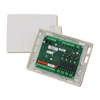
urmet domus 1043 Instruction Manual
Inputs - 4 outputs module
Hide thumbs
Also See for 1043:
- Instruction manual (25 pages) ,
- Manual (20 pages) ,
- Installation manual (17 pages)
Summary of Contents for urmet domus 1043
- Page 1 Mod. 1043 DS1043-132E LBT8298 MODULO 4 INGRESSI – 4 USCITE 4 INPUTS - 4 OUTPUTS MODULE Sch./Ref. 1043/533 LIBRETTO ISTRUZIONI INSTRUCTION MANUAL...
-
Page 2: Descrizione Generale
1043/550, 1043/560 e 1043/570. cortocircuitato il modulo invia la rispettiva La configurazione di fabbrica del modulo 1043/533 segnalazione di guasto n° 13 o n° 12 alla è impostata come quattro attuatori in modo 0. - Page 3 Modo 2 per 10 secondi il passaggio in cortocircuito Questa modalità di funzionamento è rivolta al dell’ingresso; se questo non accade il modulo all’attivazione ed al controllo di dispositivi invia la segnalazione di guasto n° 16 alla elettromeccanici (es. serrande) che necessitano centrale.
- Page 4 DS1043-132E...
- Page 5 Fig. 1 – Collegamento modulo 1043/533 come attuatore in modo 0 con disattivazione locale oppure in modo 3 per controllo sistemi (distanza massima contatto di disattivazione <10m) Fig. 2 – Collegamento modulo 1043/533 come attuatore in modo 1 (distanza max apparecchiatura da controllare <10m)
- Page 6 Fig. 3 – Collegamento modulo 1043/533 come attuatore in modo 2 (distanza max apparecchiatura da controllare <10m) 1043/533 MODULO DI INGRESSO PER CONTATTI PULITI STABILI L'uscita reset, quando abilitata Quando programmato come modulo di ingresso programmazione, consente di attivare il relè per...
- Page 7 Fig. 4 – Collegamento modulo 1043/533 come modulo d’ingresso stabile (LI) a singola soglia (distanza massima apparecchiatura di controllo <10m) Fig. 5 – Collegamento modulo 1043/533 come modulo d’ingresso stabile (LI) a multisoglia (distanza massima apparecchiatura di controllo <10m) DS1043-132E...
- Page 8 INDIRIZZAMENTO Descrizione L'indirizzo (1128) è impostato via software e Ingresso positivo linea rivelazione memorizzato su una memoria non volatile. Ingresso negativo linea rivelazione Il modulo può essere indirizzato dalla centrale in Schermo ingresso linea rivelazione modalità automatica o manuale. Schermo uscita linea rivelazione Per ulteriori dettagli si veda il manuale di Uscita negativo linea rivelazione programmazione della centrale.
-
Page 9: Caratteristiche Tecniche
10mm di protezione isolante operativa <17V dal conduttore principale inserendolo nella Verde lamp. lento morsettiera. (2s): Stato normale Il modulo 1043/533 deve essere utilizzato Verde lamp. veloce: esclusivamente con le centrali Urmet Sch. Indirizzo duplicato 1043/550,1043/560 e 1043/570. Relè uscita 1A, 30V⎓,... -
Page 10: General Description
Externally un-powered module condition. Input is not checked and the supervised output is not activated. The 1043/533 is equipped with a dry contact relay output, a supervised output and an external Mode 1 power supply input. This operating mode will be used to activate an... - Page 11 Mode 2 This operating mode will be used for activation and After 10 seconds, if the short-circuit condition of control of electro-mechanic devices (e.g. dumpers) input 1 ends, the module signals fault n° 102 to the which require some time to switch from the idle to control panel.
- Page 12 Fig. 1 – Connection for 1043/533 module configured as mode 0 actuator with local reset or mode 3 for system control (max connection length between reset contact and 1043/533 module is 10m) DS1043-132E...
- Page 13 Fig. 2 – Connections for 1043/533 module configured as mode 1 actuator (max connection length between equipment under monitoring and input is 10m) Fig. 3 – Connections for 1043/533 module configured as mode 2 actuator (max connection length between equipment under monitoring and input is 10m)
- Page 14 1043/533 INPUT MODULE LATCHED DRY CONTACTS When programmed as single threshold latched input module, the device monitors continuously the input. Independently of the input used, the other input must be correctly terminated with end of line resistor. If the end of line resistor is removed the module signals fault n°...
- Page 15 Fig. 4 – Connections for 1043/533 module configured as single threshold latched input module (LI) (max connection length between the controlled equipment and input is 10m) Fig. 5 – Connections for 1043/533 module configured as multi-threshold latched input module (LI)
-
Page 16: Terminal Boards
The address (1128) of the module is configured Detection circuit positive input via software and stored in a non-volatile memory. Detection circuit negative input The 1043/533 can be addressed, in manual or Detection circuit input shield automatic mode from the control panel. Detection circuit output shield... -
Page 17: Input Characteristics
Maximum capacitance = 2µF Electrical connection must be performed by removing approximately 10 mm of insulating cover from the main lead and insert it on the terminal block. The 1043/533 can be used with Urmet control panel ref. 1043/550, 1043/560 and 1043/570. DS1043-132E... -
Page 18: Technical Specifications
(-22 158°F) Dimensions 180x138x45mm Weight 240g Enclosure material ABS V0 Compliant with EN54-18:2005 / AC:2007 EN54-17:2005 / AC:2007 4 INPUTS / 4 OUTPUT module Mod. 1043/533 Urmet S.p.A.1293-CPD-0320 1293 DoP n. 1293-CPR-0320 Further information is available to the manufacturer. DS1043-132E... - Page 19 DIRETTIVA 2012/19/UE DEL PARLAMENTO EUROPEO E DEL CONSIGLIO del 4 luglio 2012 sui rifiuti di apparecchiature elettriche ed elettroniche (RAEE) Il simbolo del cassonetto barrato riportato sull’apparecchiatura o sulla sua confezione indica che il prodotto alla fine della propria vita utile deve essere raccolto separatamente dagli altri rifiuti. L’utente dovrà, pertanto, conferire l’apparecchiatura giunta a fine vita agli idonei centri comunali di raccolta differenziata dei rifiuti elettrotecnici ed elettronici.
- Page 20 DS1043-132E LBT8298 DS1043-132E...


Need help?
Do you have a question about the 1043 and is the answer not in the manual?
Questions and answers