Table of Contents
Advertisement
Quick Links
Z.I. La Plaine des Isles - F 89000 AUXERRE - FRANCE
Tel. : +33 (0)3.86.49.86.30 - Fax : +33 (0)3.86.49.87.17
contact@mouvex.com - www.mouvex.com
AF HT PUMP
Construction O
INSTRUCTIONS 1003-D00 e
Section
1003
Effective
September 2012
Replaces
September 2011
Original instructions
INSTALLATION
OPERATION
MAINTENANCE
Your distributor :
Advertisement
Table of Contents

Related Manuals for Dover PSG Mouvex AF HT


Summary of Contents for Dover PSG Mouvex AF HT
- Page 1 INSTRUCTIONS 1003-D00 e Section 1003 Effective September 2012 Replaces September 2011 Original instructions AF HT PUMP Construction O INSTALLATION OPERATION MAINTENANCE Your distributor : Z.I. La Plaine des Isles - F 89000 AUXERRE - FRANCE Tel. : +33 (0)3.86.49.86.30 - Fax : +33 (0)3.86.49.87.17 contact@mouvex.com - www.mouvex.com...
-
Page 2: Table Of Contents
ECCENTRIC PISTON PUMP MOUVEX PRINCIPLE SAFETY, STORAGE, INSTALLATION AND MAINTENANCE INSTRUCTIONS MODEL : AF HT USED PRESSURE UNITS Unit with suffix "g" : Unit without suffix : Gauge pressure, given regarding to atmospheric pressure Differential pressure, for example, pressure difference between (~101325 Pa, taken at 1 bar / 14,5 psi in this IOM). -
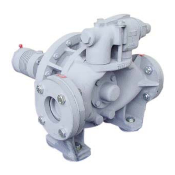
Page 3: Overall Dimensions
1. OVERALL DIMENSIONS Weight : 28 kg Noise level The sound level of a pump is greatly influenced by its condi- tions of use. Cavitation and pumping products with high gas contents generally increases the sound level. Under the following pumping conditions : •... -
Page 4: Installation
2. INSTALLATION 2.1 Choice of pump The pipes must be designed to allow thermal expansion and contraction and be firmly secured (the use of flexi- To obtain the service expected from a MOUVEX pump, ble hoses and expansion loops is recommended). regarding both performance and longevity, it is vital that We recommend placing isolating valves close to the the type of pump, its speed and the materials used for its... -
Page 5: Bypass
2. INSTALLATION (continued) 2.5 Bypass 2.7 Anchoring the pump units The correct seating of the pump is vital for its efficient WARNING operation and its longevity. The surface must be resistant enough to absorb the FAILURE TO RELIEVE THE SYSTEM stresses due to the pump unit without deformation. -
Page 6: Electric Motors
2. INSTALLATION (continued) The 3 figures below show the operation clearly. This fundamental checking of the pump must be done without any product, with the inlet and outlet circuit open Carry out a control on 4 points: to the air, for example, to avoid any risk of an unexpec- At the top - at the bottom - on the left - on the right ted pressure rise. -
Page 7: Use
3. USE 3.1 Storage 3.4 Starting-up the pump In the case of prolonged shutdown or storage, we WARNING recommend dismantling the pump and greasing it tho- roughly. If it cannot be dismantled, it should be filled with oil via its orifices (inlet and outlet) and rotated slowly by FAILURE TO RELIEVE SYSTEM PRESSURE hand to allow the oil to penetrate. -
Page 8: Opening The Pump To Inspect The Cylinder/Piston And Bushings
4. OPENING THE PUMP TO INSPECT THE CYLINDER/PISTON AND BUSHINGS Before opening the pump, always ensure that it has been drained and release the pressure it may contain. Make sure the isolation valves, if any, are closed before pulling out the drain plug 434 and its seal 412. WARNING WARNING DISCONNECTING THE FLUID OR PRES-... -
Page 9: Necessary Tools
4. OPENING THE PUMP TO INSPECT THE CYLINDER/PISTON AND BUSHINGS (continued) Serial Nbr Bypass fastening For the SEALS refer to the specified drawing WARNING To remove piston Remove the sleeve 515 by using the nut to release it. Using a screwdriver as a lever, extract the piston 301. BE CAREFUL WITH THE WEIGHT OF THE PARTS WHEN THEY ARE BEING The pumping characteristics demand a cylinder/piston... -
Page 10: Mechanical Seals
5. MECHANICAL SEALS WARNING 5.1 Operation Shaft 501 drives the rotating part 697 of the mechanical seal in a rotary motion. DISCONNECTING THE FLUID OR PRES- SURE CONTAINMENT COMPONENTS The stationary seal face 604 of the seal is fixed in the DURING PUMP OPERATION CAN CAUSE mechanical seal holder 701 with the stopper 627. -
Page 11: Reassembly
5. MECHANICAL SEALS (continued) 5.3 Reassembly • The seals 717, 739, screws 776 and 706, support washer 731, circlips 704, lip seal 707, protection 733, mechani- cal seal 600a and plug 738 must be changed whenever removed. • Thoroughly clean the part of the shaft in contact with the mechanical seal (surface must be free from scratches). -
Page 12: Bypass
6. BYPASS CAUTION Before starting the pump, make sure that it rotates in the right direction in relation to the direction in which you want the product to flow. Make sure that the bypass is positioned correctly in relation to the direction in which THE PUMP LUBRICANT IS VERY SLIPPERY the product flows (see §... -
Page 13: Inversion
6. BYPASS (continued) Loading (bar) Mini Maxi 6.3 Inversion Before commencing work, make sure that the pump cannot be started up, even accidentally. Before opening the pump, it must be drained and relieved of any pressu- WARNING re it may contain. Take care to check that the isolation valves, if any, are closed before pulling out the drain plug 434 and its seal 412. -
Page 14: Obtaining The Flow
6. BYPASS (continued) 6.5 Obtaining the flow 6.6 Energy consumption If the energy consumption does not correspond with WARNING expectations, the reason may be poor adjustment of the bypass valve. If consumption is low and you do not get the required PUMPS OPERATING AGAINST A CLOSED VALVE CAN CAUSE SYSTEM FAILURE, flow, close the discharge valve and tighten the adjust-... -
Page 15: Troubleshooting
8. TROUBLESHOOTING ZERO OR INSUFFICIENT FLOW PRELIMINARY CHECKS Make sure that the plastic plugs have been taken away from the ports of the pump and that the pump is running (defective drive, damaged motor, etc., faulty transmission : broken coupling, sliding belt, worn or poorly coupled clutch, etc.). - Page 16 8. TROUBLESHOOTING (continued) MEASURING THE VACUUM PRESSURE (as close as possible to the pump inlet, inlet side). If the vacuum is high, e.g. higher than or equal to 6 to 7 metres WC (0.6 to 0.7 bara i.e. about 45 or 50 cm of mercury), this can result in pump noise.
- Page 17 8. TROUBLESHOOTING (continued) ABNORMAL NOISES These noises can be caused by hydraulic and mechanical sources. They can be distinguished by the fact that only the former disappear (or at least lessen) when air is allowed into the inlet pipe. HYDRAULIC NOISES These noises can come from insufficient product being supplied to the pump, or : - the rotation speed is too high for the installation conditions (increase of viscosity due to a change of product or a reduction of temperature, etc.).
-
Page 18: Certificate Of Conformity
9. CERTIFICATE OF CONFORMITY NT 1003-D00 09.12 AF HT e 18/18...
Need help?
Do you have a question about the PSG Mouvex AF HT and is the answer not in the manual?
Questions and answers