Table of Contents
Advertisement
Available languages
Available languages
Quick Links
Advertisement
Chapters
Table of Contents

Related Manuals for SIKA VTY10MA


Summary of Contents for SIKA VTY10MA
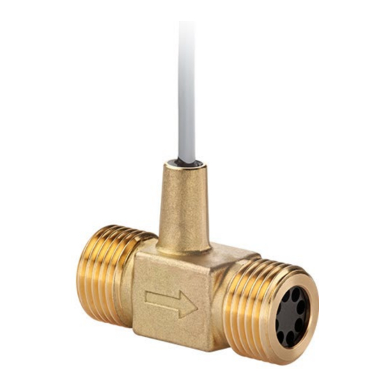
- Page 1 Betriebsanleitung ..........Seite 2 – 13 Operating manual ..........page 14 – 27 Turbinen-Durchflusssensoren VTY Turbine Flow Sensors VTY...
-
Page 2: Table Of Contents
Weitergabe sowie Vervielfältigung dieser Betriebsanleitung, Verwertung und Mitteilung ihres Inhalts sind verboten, soweit nicht ausdrücklich gestattet. Zuwiderhandlungen verpflichten zu Schadenersatz. Alle Rechte für den Fall der Patent-, Gebrauchsmuster- oder Geschmacksmustereintragung vorbehal- ten. - 2 - © SIKA • Ea7900_VTY • 05/2022... -
Page 3: Sicherheitshinweise
Sicherheitshinweise Sicherheitshinweise Lesen Sie die Betriebsanleitung sorgfältig durch. Befolgen Sie alle Anweisungen und Hin- weise, um Personen- oder Sachschäden zu vermeiden. Bestimmungsgemäße Verwendung Die Durchflusssensoren der Baureihe VTY dürfen nur zur Volumenstromerfassung oder Do- sierung von Flüssigkeiten verwendet werden. Sie dürfen nicht zur Messung von Gasen ein- gesetzt werden. -
Page 4: Einbau
Einbau Einbau WICHTIG Gasblasenbildung und Kavitation im Medium können zu Fehlfunktionen des Sen- sors führen und müssen verhindert werden. Kavitation ist stark abhängig vom Me- dium, Durchfluss und der Medientemperatur. SIKA empfiehlt folgende minimale Systemdrücke. Empfohlener minimaler Systemdruck DN10 DN15... - Page 5 Einbau Der Einbau kann sowohl in horizontalen als auch in vertikalen Rohrleitungen erfolgen. • Der Durchflusssensor ist ausschließlich für den Einsatz in komplett gefüllten Leitungen geeignet. Einen freien Auslauf müssen Sie unbedingt vermeiden. Der auf dem Durchflusssensor angebrachte Pfeil () zeigt die einzig mögliche Durch- •...
- Page 6 20 Nm 20 Nm 20 Nm SW 19 SW19 SW24 SW30 SW36 Ziehen Sie die beiden Überwurfmuttern fest. Halten Sie dabei mit einem Gabelschlüssel am Turbinen- körper des Gerätes gegen. - 6 - © SIKA • Ea7900_VTY • 05/2022...
-
Page 7: Elektrischer Anschluss
Elektrischer Anschluss Elektrischer Anschluss ® Der elektrische Anschluss erfolgt über 3 Einzeladern mit Molex Mini-Fit Stecker. Optional ist der elektrische Anschluss auch als 3-adrige PVC-Leitung verfügbar. Der VTY10 ist zusätzlich auch mit 3 Einzeladern verfügbar. Der Durchflusssensor kann auch mit kundenspezifischer Leitung, sowie mit oder ohne An- schlussverbinder geliefert werden. -
Page 8: Inbetriebnahme Und Messbetrieb
Bei einem Defekt muss das Gerät ausgetauscht oder zur Reparatur an den Hersteller zurück- geschickt werden. WICHTIG Beim Öffnen des Gerätes können wichtige Bauteile oder Komponenten beschä- digt werden. Öffnen Sie niemals das Gerät und führen Sie keine Reparaturen selbst daran durch. - 8 - © SIKA • Ea7900_VTY • 05/2022... - Page 9 WICHTIG Die Lager des Durchflusssensors können beim Ausblasen beschädigt werden. Blasen Sie den Durchflusssensor auf keinen Fall mit Druckluft aus. Rücksendung Beachten Sie die Hinweise zum Ablauf des Rücksendeverfahrens auf unserer Website (www.sika.net/service/service/rma-warenruecksendung). Technische Änderungen vorbehalten - 9 -...
-
Page 10: Demontage Und Entsorgung
Das Gerät besteht aus unterschiedlichen Werkstoffen. Es darf nicht zusammen mit Hausmüll entsorgt werden. Führen Sie das Gerät der lokalen Wiederverwertung zu oder schicken Sie das Gerät an Ihren Lieferanten bzw. SIKA zurück. * WEEE-Reg.-Nr.: DE 25976360 Medienberührende Werkstoffe VTY10MA... -
Page 11: Technische Daten
Technische Daten Technische Daten Bei kundenspezifischen Ausführungen können technische Daten gegenüber den Angaben dieser Anleitung abweichen. Bitte beachten Sie die Angaben auf dem Typenschild. 8.1 Kenndaten VTY VTY10MA VTY10K5 VTY15 VTY20 VTY25 Kenndaten Messgerät Messbereich 1...30 l/min 1...45 l/min 1…60 l/min 1…90 l/min... - Page 12 Technische Daten 8.2 Abmessungen VTY10MA Gewinde VTY10K5 Gewinde VTY15 Gewinde VTY20 Gewinde Molex Mini-Fit 23,8 - 12 - © SIKA • Ea7900_VTY • 05/2022...
- Page 13 Technische Daten VTY25 Gewinde Alternative für elektrischen Anschluss Technische Änderungen vorbehalten - 13 -...
-
Page 14: About This Operating Manual
Offenders will be held liable for the payment of damages. All rights reserved in the event of the grant of a patent, utility model or design. - 14 - © SIKA • Ea7900_VTY • 05/2022... -
Page 15: Safety Instructions
Safety Instructions Safety Instructions Read the operating manual carefully. Follow all instructions and notices to prevent injury or damage to property. Intended use The flow sensors of the series VTY may only be used for flow rate measurements or dosing of liquids. -
Page 16: Installation
IMPORTANT Bubble formation and cavitation in the medium can cause sensor malfunction and must be avoided. Cavitation is strongly dependent on the medium, flow rate and medium temperature. SIKA recommends the following minimum system pres- sures. Recommended minimum system pressure... - Page 17 Installation The unit can be installed in both horizontal as well as vertical pipelines. The flow sensor • is only suitable for use in fully filled piping. You must avoid a free outlet. The arrow which is placed on the flow monitor () shows the only permitted flow direc- •...
- Page 18 20 Nm 20 Nm 20 Nm AF19 AF19 AF24 AF30 AF36 Tighten both union nuts. When tightening, use a spanner to counter the process connection on the turbine body in place. - 18 - © SIKA • Ea7900_VTY • 05/2022...
-
Page 19: Electrical Connection
Electrical Connection Electrical Connection ® The electrical connection is made by 3 single wires with Molex Mini-Fit plug. Optionally, the electrical connection is also available with a 3-wire PVC cable. The VTY10 is additionally also available with 3 single wires. The flow sensor is also available with a customer specific cable and with or without con- nector. -
Page 20: Commissioning And Operating
IMPORTANT When opening the device, critical parts or components can be damage. Never open the device and perform any repair yourself. - 20 - © SIKA • Ea7900_VTY • 05/2022... - Page 21 The bearings of the flow sensor can be dam- aged when blowing out. Never blow out the flow sensor with com- pressed air. Return shipment Please observe the instructions for the return procedure on our website (www.sika.net/en/service/service/rma-return-of-products). Technical changes reserved - 21 -...
-
Page 22: Disassembly And Disposal
The device consists of various different materials. It must not be disposed of with household waste. Take the device to your local recycling plant send the device back to your supplier or to SIKA. * WEEE reg. no.: DE 25976360 Materials in Contact With Media... -
Page 23: Technical Data
Technical Data Technical Data The technical data of customised versions may differ from the data in these instructions. Please observe the information specified on the type plate. 8.1 Characteristics VTY Type VTY10MA VTY10K5 VTY15 VTY20 VTY25 Characteristics measurement device Measuring range 1...30 l/min... - Page 24 Technical Data 8.2 Dimensions VTY10MA Thread VTY10K5 Thread VTY15 Thread VTY20 Thread Molex Mini-Fit 23.8 - 24 - © SIKA • Ea7900_VTY • 05/2022...
- Page 25 Technical Data VTY25 Thread Alternative for electrical connection Technical changes reserved - 25 -...
- Page 26 - 26 - © SIKA • Ea7900_VTY • 05/2022...
- Page 27 Technical changes reserved - 27 -...
- Page 28 SIKA Systemtechnik GmbH Struthweg 7–9 34260 Kaufungen / Germany +49 5605 803-0 +49 5605 803-555 info@sika.net www.sika.net © SIKA • Ea7900_VTY • 05/2022...
Need help?
Do you have a question about the VTY10MA and is the answer not in the manual?
Questions and answers