
Related Manuals for Blue-White industries Sonic-Pro S6A Series


Summary of Contents for Blue-White industries Sonic-Pro S6A Series
- Page 1 Chemical Feed Flow Meter Series S6A www.blue-white.com sales@blue-white.com customerservice@blue-white.com...
-
Page 2: Table Of Contents
Page 2 ® Sonic-Pro S6A Introduction Product Overview Product Specifications Features Agency Listings Unpacking ® Installing Blue-Central Connecting the Meter Configuration Dashboard Settings 6.2.1 Edit Settings About Screen Device Summary Setup and Configure 6.5.1 General 6.5.2 Faults and Warnings 6.5.3 Relay Output 6.5.4 Frequency Output... - Page 3 Page 3 ® Sonic-Pro S6A READ THE INSTRUCTION MANUAL PRIOR TO INSTALLATION AND USE.
-
Page 4: Introduction
Page 4 ® Sonic-Pro S6A 1.0 Introduction Thank you for purchasing the S6A Chemical Feed Flowmeter. This Operating Manual provides important information regarding the safe installation, operation, and maintenance of the meter. Please read it carefully before attempting to install or operate the meter. A copy of this Manual should be kept by the operator. - Page 5 Page 5 ® Sonic-Pro S6A 2.0 Product Specifications (continued) Accuracy Charts: S6A1 ACCURACY RANGE 5500 5000 4500 4000 3500 3000 2500 2000 1500 1000 1000 2000 2500 3000 3500 4000 4500 5000 1500 ACTUAL 12.5% Sodium Hypochlorite 25% Fluorosilicic acid S6A2 ACCURACY RANGE 11000 10000...
- Page 6 Page 6 ® Sonic-Pro S6A Digital Drawdown Accuracy Charts: Below are the meter accuracy charts after a Digital Drawdown has been performed (see page 16, section 9.0). S6A1 DIGITAL DRAWDOWN ACCURACY S6A2 DIGITAL DRAWDOWN ACCURACY...
-
Page 7: Features
Page 7 ® Sonic-Pro S6A 2.1 Features Inline pipe fittings for easy installation Ÿ ® Configurable via Blue-Central desktop software Ÿ Isolated 4-20 mA output - fully configurable Ÿ 0-10000Hz Pulse output - fully configurable Ÿ User configurable flow rate and total set-point triggers Ÿ... -
Page 8: Configuration
Huntington Beach CA 92649 DASHBOARD Electron Version: 2.0.0 Contact: techsupport@blue-white.com contact information for Blue-White Industries, as well as Release Note: Phone: 714-893-8529 SETTINGS - Fix a bug that caused the firmware upgrade process to submit feedback by left-clicking the Share your Ideas and... -
Page 9: Device Summary
Page 9 ® Sonic-Pro S6A 6.4 Device Summary Name The Device Summary screen gives the user a basic overview of the meter’s settings and Actions status. Blue-White’s S6A Series To access the meter’s Device Summary Device Summary screen, left-click the device name. Alternatively, the user can hover the mouse cursor over the corresponding Action button on the Dashboard and left click Device... -
Page 10: General
Page 10 ® Sonic-Pro S6A 6.5.1 General To edit the General Configuration left-click the General tab on the Setup and Configure screen. Name: Edit the Name of the S6A meter by clicking in the Name field. Name This will help to quickly identify which meter is being configured in Blue-White’s S6A Series ®... -
Page 11: Faults And Warnings
Page 11 ® Sonic-Pro S6A 6.5.2 Faults and Warnings To edit the Faults and Warnings settings the user must left-click Warnings the Faults and Warnings tab on the Setup and Configure screen. Bubbles (W2) In the Faults and Warnings screen the user can configure how the Continue Operation meter will respond to various Error Conditions by left-clicking in the appropriate drop-down menu and selecting between Continue... -
Page 12: Relay Output
Page 12 ® Sonic-Pro S6A 6.5.3 Relay Output To edit the Relay Output settings the user must left-click the Relay Output tab on the Setup and Configure screen. Here the user can select the Operation Mode (Flow Rate or Totalizer) and Switch Operation (if the relay will open or close when triggered). -
Page 13: Frequency Output
Page 13 ® Sonic-Pro S6A 6.5.4 Frequency Output To edit the Frequency Output settings the user Flow Rate Range in (mL/m) must left-click the Frequency Output tab on the 5000 Setup and Configure screen. These selectable fields are used to send a high Frequency Output Range in Hz speed frequency signal to an external device 1000... -
Page 14: Pulse Output
Page 14 ® Sonic-Pro S6A 6.5.6 Pulse Out Volume per Pulse (mL) To edit the Pulse Out settings the user must left-click the Pulse Output tab on the Setup and Configure screen. These selectable fields are used to send a pulse signal for a Pulse Duration (milliseconds) specified duration (Pulse width) to an external device such as a ProSeries pump for any specified volume (Volume per Pulse). -
Page 15: Upgrade Firmware
Page 15 ® Sonic-Pro S6A 7.0 Upgrade Firmware To download and install the latest firmware left-click Upgrade Firmware on Upgrade Firmware the right sidebar of the Device Summary Screen. The user will be taken to the Latest Firmware Blue-Central® screen. Left-click Start Upgrade on the right Dashboard Blue-White’s S6A Series Firmware Upgrade... -
Page 16: Factory Reset
Page 16 ® Sonic-Pro S6A 8.0 Factory Reset To restore the meter to the factory default settings and firmware the user must Factory Reset perform a Factory Reset. To do so, on the Device Summary screen, left-click Factory Reset located on the right sidebar. The Factory Reset dialog box will appear. -
Page 17: Digital Drawdown
Page 17 ® Sonic-Pro S6A 9.0 Digital Drawdown Digital Drawdown allows the user to increase the accuracy of the meter at a targeted Digital Drawdown feed rate. To access the Digital Drawdown screen, left-click Digital Drawdown on right sidebar of the Device Summary screen. Note: This is an optional feature and not required for the meter to function properly. -
Page 18: Customize Chemical Calibration
Page 18 ® Sonic-Pro S6A 9.1 Customize Chemical Calibration Custom Chemical Calibration can be used to configure the S6A meter to a chemical that is not listed among the Pre- Calibrated Chemical Profiles (see page 3, section 2.0). ! CAUTION •... - Page 19 Page 19 ® Sonic-Pro S6A Step 3: Select Digital Drawdown. Digital Drawdown Step 4: With the meter properly installed in the system and connected to a desktop or laptop computer, the user must establish Known Flowrate of the system by performing a draw down test. Step 5: Enter Known Flowrate into the Known Flowrate field on the Digital Drawdown screen.
- Page 20 Page 20 ® Sonic-Pro S6A Step 7: Navigate to the System Information screen to verify the Custom Chemical Calibration was successful Step 8: Check if all the Error lights are off under the Errors & Warnings Settings section of the System Information screen. If one of the error lights are active then the calibration was unsuccessful.
-
Page 21: System Information
Page 21 ® Sonic-Pro S6A 10.0 System Information To enter the System Information screen, click System Information on the System Information ride sidebar of the Device Summary screen. In the System Information screen the user can view General information, Digital Drawdown status, Frequency Output settings, 4-20 Output settings, Pulse Output settings, Relay Output settings, Flow Rate, Totalized Flow, Signal Levels (for advanced users and technical support), and Error &... -
Page 22: Wiring Installation
Page 22 ® Sonic-Pro S6A 11.0 Wiring Installation The meter must be powered by 5 volts DC. Wattage must not exceed 5 watts. DO NOT power the unit by both the transformer and USB cable. 20-24 AWG (American wire gauge) shielded cable is recommended for signal output connections. 11.1 Cable Gland Liquid-Tight Connections The S6A wiring compartment is equipped with: Two communications cable liquid-tight cable gland grommets for cable diameters from .190 to .205 inches. -
Page 23: Fvs Wiring Guide - S6A To Proseries-M Pump
Page 23 ® Sonic-Pro S6A 11.3 FVS Wiring Guide - S6A to ProSeries Pump The following section is a step-by-step guide on wiring an S6A Chemical Feed Flowmeter to a ProSeries metering pump as a Flow Verification Sensor (FVS). What you’ll need: 16-24 AWG shielded cable Ÿ... - Page 24 Page 24 ® Sonic-Pro S6A Step 3. Trim the bare and connect the RED WIRE to the left positive PIN 1 and the BLACK WIRE to the right negative PIN 2 on the FREQUENCY terminal on the S6A circuit board. 4-20mA RELAY FREQ...
-
Page 25: S6A Remote Mount Display
Page 25 ® Sonic-Pro S6A 12.0 S6A Remote Mount Display The S6A Remote Mount Display includes a power supply and is pre-wired at the factory. 12.1 Display Terminal Configuration Terminal Function POWER Positive (+) power input (black with stripe wire from 5VDC plug-in transformer and red wire to S6A meter) 5VDC Ground (-) power input (black wire from 5VDC plug-in transformer and black wire to S6A meter) 5 WATTS MAX... -
Page 26: Wiring S6A Remote Mount Display To S6A Meter Body
Page 26 ® Sonic-Pro S6A 12.2 Wiring S6A Remote Mount Display to S6A meter Body Connecting Frequency Output Connect the frequency cable RED OR YELLOW WIRE to pin 1 and the BLACK WIRE to PIN 2 of the terminal marked FREQ on the S6A meter circuit board. -
Page 27: Mounting The S6A Remote Mount Display
Page 27 ® Sonic-Pro S6A 12.3 Mounting The Remote Mount Display Panel Mount Optional Pipe and Wall Mount Adapter Kit Wall Mount Wall Mount Kit Ordering Information Kit Number Decription 71000-301 Wall Mount Kit Pipe Mount Kit Ordering Information Pipe Mount Kit Number Decription 71000-302... -
Page 28: Programming The S6A Remote Mount Display
Page 28 ® Sonic-Pro S6A 13.0 Programming the Remote Mount S6A Display The S6A Display will use the FREQUENCY (Hz) output signal from the S6A meter to calculate and display flow. Once the FREQUENCY output signal parameters are configured in the S6A meter, the S6A display rate scale factor and total scale factors can then be calculated and programmed into the S6A Display. -
Page 29: S6A Suggested Default Display Calibration Constants
Page 29 ® Sonic-Pro S6A 13.2.1 S6A Suggested Default Display Calibration Constants The following default S6A Remote Mount Display calibration constants should be used for most applications in ml/min, GPH or LPH. These values must be programmed into the display unit. Screen No. -
Page 30: Determine The Decimal Total Factor
Page 30 ® Sonic-Pro S6A 13.2.4 Determine the Decimal Total Factor Desired Location = D (Decimal Total Factor) Note: Four decimal places maximum. 00000 = 0000.0 = 000.00 = 00.000 = 1000 0.0000 = 10000 13.2.5 Determine the Time Factor Time Factor = t Example: Per Minute =... -
Page 31: Programming S6A Remote Mount Display (Step By Step Guide)
Page 31 ® Sonic-Pro S6A 14.0 Programming the S6A Remote Mount Display (step by step guide) Note: While in the programming mode, if no buttons are pressed within twenty seconds, the programming mode is automatically exited without saving the input of the last screen. (values for model S6A11 in GPH are shown in the illustrations below) Step 1: Entering the Rate Scale Factor. -
Page 32: Installation
Page 32 ® Sonic-Pro S6A 15.0 Installation The S6A Chemical Feed Flowmeter is designed to withstand outdoor conditions. A cool, dry location, where the unit can be easily monitored is recommended. Special ventilation is not required. 15.1 Mounting Location For the S6A Chemical Feed Flowmeter to operate properly the pipe must be full, therefore it must be installed in a vertical position with fluid flowing in an upward direction. -
Page 33: Product Dimensions
Page 33 ® Sonic-Pro S6A Installation Requirements: Ceiling 1. Mounting Direction can cause inaccuracies! Meter must be installed in a vertical plane with fluid flowing in an upward direction to ensure accuracy. 2. Vibration and heavy loads will damage the meter! Wall, floor and ceiling mounts and supports must be carefully aligned with the meter body and sturdy enough to support the plumbing and prevent vibration. -
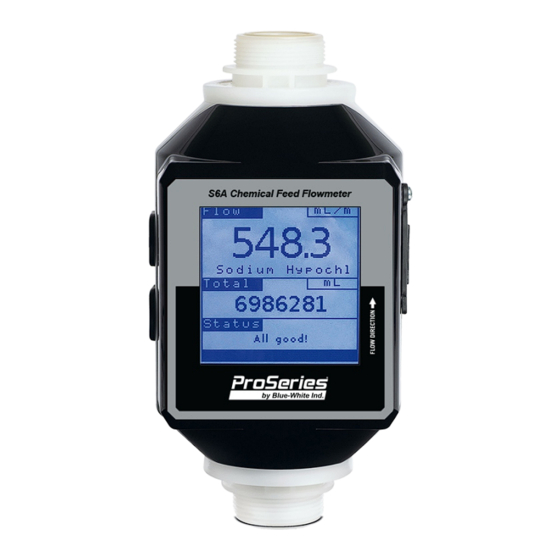
Page 34: Lcd Display For Meter Mount Display Model
Page 34 ® Sonic-Pro S6A 17.0 LCD Display for Meter Mount Display Model The meter mount display model of the S6A Chemical Feed Flowmeter comes equipped with a 3.5” LCD display that will indicate the flow rate, totalized flow, and status of the device. Unit of Volume Flow Rate Flow... -
Page 35: Troubleshooting
W3 - Yellow WARNING Light - Power cycle meter Hardware failure has occurred. F1 - Red FAULT Light - If problem persists, contact Blue-White Industries (System Failure) Ph: 714-893-8529 - Prime system to fill the meter Fluid is not present in the meter. -
Page 36: Replacement Parts
Page 36 ® Sonic-Pro S6A 20.0 Replacement parts ITEM NO. PART NUMBER DESCRIPTION 20.1 S6A Power Supply Kit 90008-723 U.K. Blade Power Supply (part number 72000-594) 90008-513 Europe Blade Power Supply 90008-724 Australian Blade Power Supply 90008-743 Power Supply 120AC/5VDC 2000MA 90010-597 USB A-C Cable... -
Page 37: S6A Fittings Kit
Page 37 ® Sonic-Pro S6A ITEM NO. PART NUMBER DESCRIPTION 20.2 S6A Fittings Kit 76001-855 Adapter S6A PVC w/AFLAS O-Ring (part number 72000-588) w/EP O-Ring (part number 72000-647) 90003-565 Cable Gland 90003-577 O-Ring 2-119 AFLAS 90003-153 O-Ring 2-119 EP 91001-296 Adapter Elbow, .50 MNPT 91001-295 .50”... -
Page 38: Appendix A: Product Matrix
Page 38 ® Sonic-Pro S6A APPENDIX : A Product Matrix Chemical Feed Flowmeter Model Number S6A Chemical Feed Flowmeter Flow Range 10-5000 mL/min (0.158-79.2 GPH) 100-10000 mL/min (1.58 -158.5 GPH) Display options Remote Mount Display Meter Mount Display Elastomer Material (O-Rings) TFE/P meter Fittings Standard Equipment - Includes 1/2”... -
Page 39: Appendix B: Warranty
Page 39 ® Sonic-Pro S6A APPENDIX : B Warranty Limited Warranty ! Blue-White S6A meters are warranted to be free from defects in material and workmanship for 24 months from date of factory shipment. WARRANTY COVERAGE IS LIMITED TO REPAIR OR REPLACEMENT OF THE DEFECTIVE meter ONLY. - Page 40 Users of electrical and electronic equipment (EEE) with the WEEE marking per Annex IV of the WEEE Directive must not dispose of end of life EEE as unsorted municipal waste, but use the collection framework available to them for the return, recycle, recovery of WEEE and minimize any potential effects of EEE on the environment and human health due to the presence of hazardous substances.
Need help?
Do you have a question about the Sonic-Pro S6A Series and is the answer not in the manual?
Questions and answers