Table of Contents
Advertisement
Copyright
This publication, including all photographs, illustrations and software, is protected un-
der international copyright laws, with all rights reserved. Neither this manual, nor any
of the material contained herein, may be reproduced without written consent of the au-
thor.
Version 7.3
Disclaimer
The information in this document is subject to change without notice. The manufac-
turer makes no representations or warranties with respect to the contents hereof and
specifically disclaims any implied warranties of merchantability or fitness for any par-
ticular purpose. The manufacturer reserves the right to revise this publication and to
make changes from time to time in the content hereof without obligation of the manu-
facturer to notify any person of such revision or changes.
Trademark Recognition
Microsoft, MS-DOS and Windows are registered trademarks of Microsoft Corp.
MMX, Pentium, Pentium-II, Pentium-III, Celeron are registered trademarks of Intel
Corporation.
Other product names used in this manual are the properties of their respective owners
and are acknowledged.
Federal Communications Commission (FCC)
This equipment has been tested and found to comply with the limits for a Class B digi-
tal device, pursuant to Part 15 of the FCC Rules. These limits are designed to provide
reasonable protection against harmful interference in a residential installation. This
equipment generates, uses, and can radiate radio frequency energy and, if not in-
stalled and used in accordance with the instructions, may cause harmful interference
to radio communications. However, there is no guarantee that interference will not oc-
cur in a particular installation. If this equipment does cause harmful interference to
radio or television reception, which can be determined by turning the equipment off
and on, the user is encouraged to try to correct the interference by one or more of the
following measures:
−
Reorient or relocate the receiving antenna.
−
Increase the separation between the equipment and the receiver.
−
Connect the equipment onto an outlet on a circuit different from that to which
the receiver is connected.
−
Consult the dealer or an experienced radio/TV technician for help.
Shielded interconnect cables and a shielded AC power cable must be employed with
this equipment to ensure compliance with the pertinent RF emission limits governing
this device. Changes or modifications not expressly approved by the system's manu-
facturer could void the user's authority to operate the equipment.
i
Preface
Advertisement
Table of Contents

Related Manuals for ECS P4VMM2


Summary of Contents for ECS P4VMM2
- Page 1 Preface Copyright This publication, including all photographs, illustrations and software, is protected un- der international copyright laws, with all rights reserved. Neither this manual, nor any of the material contained herein, may be reproduced without written consent of the au- thor.
- Page 2 Declaration of Conformity This device complies with part 15 of the FCC rules. Operation is subject to the follow- ing conditions: − This device may not cause harmful interference, and − This device must accept any interference received, including interference that may cause undesired operation.
-
Page 3: Table Of Contents
Preface CHAPTER 1 Introducing the Mainboard Introduction ....................1 Checklist .....................1 Standard Items ....................1 Features .....................1 Choosing a Computer Case ...............4 Mainboard Components ................5 CHAPTER 2 Installing the Mainboard Mainboard Installation.................7 Installing the Processor ................8 Installing Memory Modules .................9 Checking Jumper Settings ................11 Connecting Case Components ..............13 The Panel Connectors.................. - Page 4 CHAPTER 4 Using the Mainboard Software About the Software CD-ROM ..............32 Auto-installing under Windows 98/ME/2000/XP ........32 Running Setup ....................33 Manual Installation..................35 Utility Software Reference ................35...
-
Page 5: Introducing The Mainboard
Introducing the Mainboard Thank you for choosing the P4VMM2 mainboard. This mainboard has a Socket 478 for the Intel Pentium 4 type of processors supporting front side bus (FSB) speeds up to 533/400 MHz. This mainboard incorporates the VIA P4M266/A Northbridge and VT8235 Southbridge chipsets that support AC 97 audio codec, and provide Ultra DMA 133/100/66/33 function. - Page 6 Processor The P4VMM2 mainboard uses a mPGA478 Socket that has the following features: • Accommodates Intel Pentium 4 478-pins CPU • Supports a front-side bus (FSB) of 400/533 MHz Chipset The P4M266/A Northbridge and VT8235 Southbridge in this chipset in accordance with an innovative and scalable archi- tecture with proven reliability and performance.
- Page 7 with transfer rates of 33/66/100/133 MB/sec • An AGP slot • One CNR (Communications and Networking Riser) slot Integrated I/O The mainboard has a full set of I/O ports and connectors: • Two PS/2 ports for mouse and keyboard • One serial port •...
-
Page 8: Choosing A Computer Case
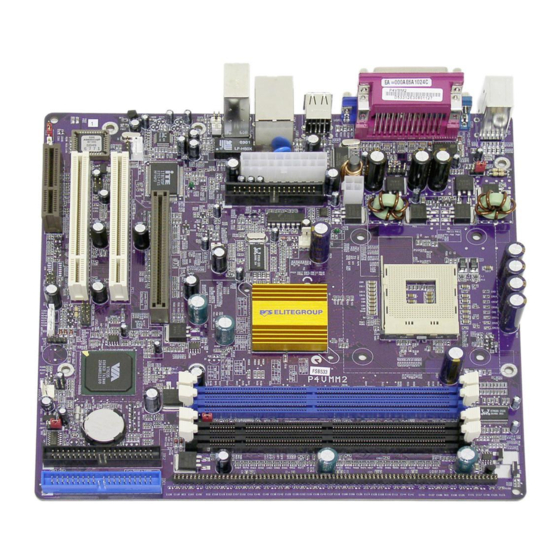
There are many types of computer cases on the market. The mainboard com- plies with the specifications for the Micro-ATX system case. Some features on the mainboard are implemented by cabling connectors on the mainboard to indicators and switches on the system case. Ensure that your case supports all the features required. - Page 10 Table of Mainboard Components Label Component AGP1 Accelerated Graphics Port BAT1 Three volt realtime clock battery Primary CD-in connector Secondary CD-in connector Standard power connector CNR1 Communications Networking Riser slot CPU SOCKET Micro PGA 478-pin socket for Pentium 4 CPUs CPU_FAN Cooling fan for CPU DDR1 ~ DDR2...
-
Page 11: Installing The Mainboard
Installing the Mainboard To install this mainboard in a system, please follow these instructions in this chapter: • Identify the mainboard components • Install a CPU • Install one or more system memory modules • Make sure all jumpers and switches are set correctly •... -
Page 12: Installing The Processor
This mainboard has a Socket 478 processor socket. When choosing a proc- essor, consider the performance requirements of the system. Performance is based on the processor design, the clock speed and system bus frequency of the processor, and the quantity of internal cache memory and external cache memory. -
Page 13: Installing Memory Modules
Apply thermal grease on top of the CPU. Put the CPU Fan down on the retention module and snap the four reten- tion legs of the cooling fan into place. Flip the levers over to lock the heat sink in place. Connect the CPU Cool- ing Fan power cable to the CPUFAN1 connec-... -
Page 14: Installation Procedure
Installation Procedure Refer to the following to install the memory modules. This mainboard supports unbuffered DDR SDRAM only. Do not attempt to insert any other type of DDR SDRAM into the slots. Push the latches on each side of the DIMM slot down. Align the memory module with the slot. -
Page 15: Checking Jumper Settings
Use the mainboard jumpers to set system configuration options. Jumpers with more than one pin are numbered. When setting the jumpers, ensure that the jumper caps are placed on the correct pins. The illustrations below show a 2-pin jumper. This illustration shows a 3-pin When the jumper cap is placed on both pins, jumper. - Page 16 JBAT1: Clear CMOS Jumper This jumper is to clear the contents of CMOS memory. You may need to clear the CMOS memory if the settings in the Setup Utility are incorrect that pre- vents your mainboard from operating. To clear the CMOS memory, disconnect all the power cables from the mainboard and then move the jumper cap into the CLEAR setting for a few seconds.
-
Page 17: Connecting Case Components
After you have installed the mainboard into a case, you can begin connecting the mainboard components. Refer to the following: Connect the Pentium 4 processor auxiliary case power supply connector to PJ1. Connect the standard power supply connec- tor to CN5. Connect the CPU cooling fan cable to CPU_FAN. -
Page 18: The Panel Connectors
CPU_FAN1/SYSTEM_FAN: FAN Power Connectors Signal Name Function System Ground +12V Power +12V Sense Sensor SPK1: Internal speaker Signal Name SPKR The Panel Connectors PANEL1 If there is a headphone jack or a microphone jack on the front panel, connect the cables to the PANEL1 on the mainboard. Signal Name Signal Name MIC IN... -
Page 19: Floppy Diskette Drive Installation
J16: LAN LED Indicator This connector is attached to LAN device that needs a LED indicator. Device Pins Link LED 1, +2 LINK LED ACT LED +3, 4 ACT LED Note: The plus sign (+) indicates a pin which must be connected to a positive voltage. -
Page 20: Installing Add-On Cards
Installing Add-on Cards The slots in this mainboard are designed to hold expansion cards and connect them to the system bus. Expansion slots are a means of adding or enhancing the mainboard’s features and capabilities. With these efficient facilities, you can increase the mainboard’s capabilities by adding hardware which performs tasks that are not part of the basic system. -
Page 21: Connecting Optional Devices
Connecting Optional Devices Refer to the following for information on connecting the mainboard’s optional devices: USB2: Front panel USB ports The mainboard has USB ports installed on the rear edge I/O port array. Addi- tionally, some computer cases have USB ports at the front of the case. If you have this kind of case, use auxiliary USB connectors USB2 to connect the front-mounted ports to the mainboard. - Page 22 SIR1: Serial infrared port The mainboard supports a Serial Infrared (IR1) data port. Infrared ports allow the wireless exchange of information between your computer and similarly equipped devices such as printers, laptops, Personal Digital Assistants (PDAs), and other computers. Signal Name Function Not assigned Not assigned...
-
Page 23: Connecting I/O Devices
CD1/CD2: CD-ROM/DVD Audio Input Connector If you have installed a CD-ROM drive or DVD-ROM drive, you can connect the drive audio cable to the onboard sound system. On the mainboard, locate the two 4-pin connectors CD1 and CD2. There are two kinds of connector because different brands of CD-ROM drive have different kinds of audio cable connectors. -
Page 24: External Connector Color Coding
External Connector Color Coding Many connectors now use standard colors as shown in the table below. Connector Color Audio line-in Light blue Audio line-out Lime Digital monitor/flat panel White Microphone Pink MIDI/game Gold Parallel Burgundy PS/2-compatible keyboard Purple PS/2-compatible mouse Green Serial Teal or Turquoise... -
Page 25: Using Bios
Using BIOS The computer uses the latest AMI BIOS with support for Windows Plug and Play. The CMOS chip on the mainboard contains the ROM setup instructions for configuring the mainboard BIOS. The BIOS (Basic Input and Output System) Setup Utility displays the system's configuration status and provides you with options to set system parameters. -
Page 26: Entering The Setup Utility
Entering the Setup Utility When you power on the system, BIOS enters the Power-On Self Test (POST) routines. POST is a series of built-in diagnostics performed by the BIOS. After the POST routines are completed, the following message appears: Press DEL to enter SETUP Pressing the delete key accesses the BIOS Setup Utility: AMIBIOS SIMPLE SETUP UTILITY –... -
Page 27: Standard Cmos Features
Some options (marked with a triangle ) lead to submenus that enable you to change the values for the option. Use the cursor arrow keys to scroll through the items in the submenu. In this manual, default values are enclosed in parenthesis. Submenu items are denoted by a triangle Standard CMOS Features This option displays basic information about your system. -
Page 28: Advanced Setup Page
Advanced Setup Page This option defines advanced information about your system. AMIBIOS SETUP – ADVANCED SETUP ©2000 American Megatrends, Inc. All Rights Reserved Quick Boot Enabled AGP Aperture Size 64MB Boot Device IDE-0 Auto detect DIMM/PCI Clk Enabled Boot Device Floppy CLK Gen Spread Spectrum Disabled... - Page 29 Password Check If you have entered a password for the system, use this item to determine, if the password is required to enter the Setup Utility (Setup) or required both at start-up and to enter the Setup Utility (Always). Boot to OS/2 > 64MB Enable this item if you are booting the OS/2 operating system and you have more than 64MB of system memory installed.
-
Page 30: Power Management Setup Page
AGP Aperture Size This item defines an AGP for the graphics. Leave this item at the default value 64MB. Auto detect DIMM/PCI Clock When this item is enabled, BIOS will disable the clock signal of free DIMM/PCI slots. CLK GEN Spread Spectrum Use this item to set the system bus spread spectrum for the installed proces- sor. -
Page 31: Pci / Plug And Play Setup Page
Hard Disk Time Out This item sets up the timeout to power down the hard disk drive, if there is no hard disk activity after passing the preset period of time. Resume On RTC Alarm / Date / Hour / Minute / Second The system can be turned off with a software command. -
Page 32: Load Optimal Settings
use of a second display card installed in a PCI slot. Allocate IRQ for PCI VGA If this item is enabled, an IRQ will be assigned to the PCI VGA graphics sys- tem. You set this value to No to free up an IRQ. PCI IDE BusMaster This item enables or disables the DMA under DOS mode. - Page 33 OnBoard FDC Use this item to enable or disable the onboard floppy disk drive interface. OnBoard Serial PortA Use this item to enable or disable the onboard COM1 serial port, and to as- sign a port address. OnBoard IR Port Use this item to enable or disable the onboard infrared port, and to assign a port address.
-
Page 34: Cpu Pnp Setup Page
ThumbDrive Support For DOS Enable this item to make a small portion of memory storage device for the USB ports. CPU PnP Setup Page This page helps you manually configure the mainboard for the CPU. The sys- tem will automatically detect the type of installed CPU and make the appropriate adjustments to the items on this page. -
Page 35: Change Password
CPU / System Temperature These items display CPU and system temperature measurement. FANs & Voltage Measurements These items indicate cooling fan speeds in RPM and the various system volt- age measurements. Change Password If you highlight this item and press Enter, a dialog box appears that you can enter a Supervisor password. -
Page 36: Using The Mainboard Software
Using the Mainboard Software The support software CD-ROM that is included in the mainboard package contains all the drivers and utility programs needed to properly run the bun- dled products. Below you can find a brief description of each software program, and the location for your mainboard version. -
Page 37: Running Setup
Setup Tab Setup Click the Setup button to run the software installation program. Select from the menu which software you want to install. Browse The Browse CD button is the standard Windows command that allows you to open Windows Explorer and show the contents of the support CD. - Page 38 Note: The following screens are examples only. The screens and driver lists will be different according to the mainboard you are installing. The mainboard identification is located in the upper left-hand corner. Click Next. The following screen appears: Check the box next to the items you want to install. The default options are recommended.
-
Page 39: Manual Installation
Insert the CD in the CD-ROM drive and locate the PATH.DOC file in the root directory. This file contains the information needed to locate the drivers for your mainboard. Look for the chipset and mainboard model; then browse to the directory and path to begin installing the drivers. - Page 40 We strongly recommend users to install this free anti-virus software to help protect your system against viruses. MediaRing Talk – Telephony Software To install the MediaRing Talk voice modem software for the built-in modem, go directory \UTILITY\MEDIARING TALK, then MRTALK- SETUP72.EXE to install the application software.
Need help?
Do you have a question about the P4VMM2 and is the answer not in the manual?
Questions and answers