Table of Contents
Advertisement
Quick Links
UG-2021-20
48V Battery Switch Reference Design
R 48V BATT Switch10
About this document
Scope and purpose
This document describes how to use the 48V battery switch reference design R 48V BATT SWITCH10.
The 48V battery switch reference design shows an implementation of an air-cooled high current disconnect
switch for automotive 48 V batteries with hall sensor and shunt based current measurement using the following
Infineon components:
OptiMOS™-5 Power-Transistors IAUT300N08S5N011 and IAUZ40N10S5N130
48V dual channel high-side MOSFET gate driver 2ED4820-EM with SPI
Hall based current sensor TLE4972-AE35D5
Intended audience
Users of the 48V battery switch reference design R 48V BATT SWITCH10.
Reference Board/Kit
Product(s) embedded on a PCB, with focus on specific applications and defined use cases that can include
Software. PCB and auxiliary circuits are optimized for the requirements of the target application.
Note:
Boards do not necessarily meet safety, EMI, quality standards (for example UL, CE) requirements.
User Guide
www.infineon.com
Please read the Important notice and the Safety precautions and the Warnings
page 1 of 46
Rev. 1.0
2022-03-09
Advertisement
Table of Contents

Subscribe to Our Youtube Channel
Related Manuals for Infineon R 48V BATT Switch10


Summary of Contents for Infineon R 48V BATT Switch10
-
Page 1: About This Document
About this document Scope and purpose This document describes how to use the 48V battery switch reference design R 48V BATT SWITCH10. The 48V battery switch reference design shows an implementation of an air-cooled high current disconnect switch for automotive 48 V batteries with hall sensor and shunt based current measurement using the following Infineon components: OptiMOS™-5 Power-Transistors IAUT300N08S5N011 and IAUZ40N10S5N130... -
Page 2: Important Notice
The customer is obliged to ensure that the use of the Evaluation Boards and Reference Boards does not cause any harm to persons or third-party property. The Evaluation Boards and Reference Boards and any information in this document is provided "as is" and Infineon Technologies disclaims any warranties, express or implied, including but not limited to warranties of non- infringement of third-party rights and implied warranties of fitness for any purpose, or for merchantability. -
Page 3: Safety Precautions
48V Battery Switch Reference Design R 48V BATT Switch10 Safety precautions Safety precautions Note: Please note the following warnings regarding the hazards associated with development systems. Table 1 Safety precautions Caution: The heatsink and the device surfaces of the evaluation or reference board may become hot during testing. -
Page 4: Table Of Contents
48V Battery Switch Reference Design R 48V BATT Switch10 Table of contents Table of contents About this document ........................1 Important notice ..........................2 Safety precautions .......................... 3 Table of contents ..........................4 The kit at a glance ........................5 Scope of supply ............................ -
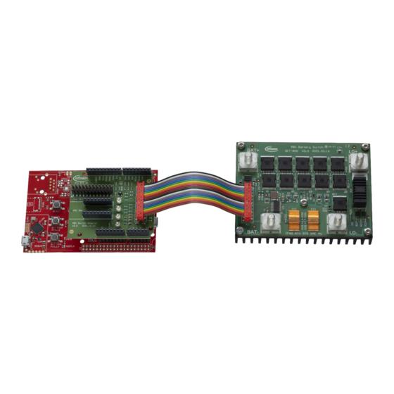
Page 5: The Kit At A Glance
48V Battery Switch Reference Design R 48V BATT Switch10 The kit at a glance The kit at a glance Scope of supply The 48V battery switch reference design consists of Power board mounted on a heatsink Adaptor board in Arduino shield form factor ... -
Page 6: Block Diagram
48V Battery Switch Reference Design R 48V BATT Switch10 The kit at a glance Block diagram The design of the switch revolves around the 2 channel MOSFET gate driver 2ED4820-EM. Channel A is used to control the power MOSFETs for (dis-)connecting the battery. Channel B drives the MOSFETs for the DC-link precharge circuit. -
Page 7: Technical Data
48V Battery Switch Reference Design R 48V BATT Switch10 The kit at a glance Technical data Table 2 System parameters Parameter Symbol Comment Value Unit Board size power board L x W x H Including heat sink 75 x 100 x 31 mm... -
Page 8: System And Functional Description
48V Battery Switch Reference Design R 48V BATT Switch10 System and functional description System and functional description Getting started Connecting supply and load The 48 V supply has to be connected to the M6 screw terminals marked “BAT+” and “BAT- “. The BAT- terminal is the ground reference of the board. -
Page 9: Description Of The Functional Blocks
48V Battery Switch Reference Design R 48V BATT Switch10 System and functional description Compatibility with other microcontroller boards By default, the reference kit comes equipped with the XMC4700 Relax Lite Kit. However, thanks to the adaptor board in Arduino shield form factor the switch can also be connected to other Arduino UNO compatible microcontroller boards like the AURIX TC375 Lite Kit. -
Page 10: Precharge Circuit
48V Battery Switch Reference Design R 48V BATT Switch10 System and functional description control of the five MOSFET pairs by a single gate driver channel and leaves the second gate driver channel of the 2ED4820-EM available for the control of the precharge circuit. -
Page 11: Mosfet Gate Driver
48V Battery Switch Reference Design R 48V BATT Switch10 System and functional description parallel to the power switch. The 2ED4820-EM gate driver channel B is driving a pair of IAUZ40N10S5N130 MOSFETs to turn the prechargarging path ON and OFF. The precharge current is limited by a 10 W power resistor. -
Page 12: Shunt Based Current Sensing
48V Battery Switch Reference Design R 48V BATT Switch10 System and functional description In general, all the extensive diagnosis as well as configuration and control of the gate driver is handled via the SPI interface. Figure 9 Dual channel MOSFET gate driver 2ED4820-EM 2.2.5... - Page 13 48V Battery Switch Reference Design R 48V BATT Switch10 System and functional description �� ��ℎ������ �� ���� ��ℎ������ Since resistors placed in series to the amplifier inputs will influence the gain factor they should be kept as small �� 0.9 ����...
-
Page 14: Hall Based Current Sensor
48V Battery Switch Reference Design R 48V BATT Switch10 System and functional description 2.2.6 Hall based current sensor In addition to the shunt based current measurement there is a hall based current sensor implemented to provide an alternative current monitoring path for improved functional safety. It is located on the high side, directly after the BAT+ input terminal. - Page 15 48V Battery Switch Reference Design R 48V BATT Switch10 System and functional description At the location of the hall probes this structure yields a magnetic field strength of ~45 µT/A. This so-called current rail transfer factor can be determined either by simulation or by measuring the output voltage of the hall sensor at a given current and using the selected sensitivity range value from the data sheet (in mV/mT) to calculate the transfer factor in µV/A.
-
Page 16: Freewheeling
48V Battery Switch Reference Design R 48V BATT Switch10 System and functional description The fast overcurrent detection output OCD of the current sensor can be connected to the SAFESTATEN pin of the gate driver in order to provide a second switch off path for overcurrent events. To enable this functionality the solder jumper on the adaptor board has to be bridged as shown in Figure 15. -
Page 17: Microcontroller Interface
48V Battery Switch Reference Design R 48V BATT Switch10 System and functional description 2.2.8 Microcontroller interface The 20-pin connector X11 provides the interface of the power board to the microcontroller. For the connector pin assignment see Table 5 below. Figure 18 shows the port and pin assigment of those signals for the microcontroller. -
Page 18: Basic Operation
48V Battery Switch Reference Design R 48V BATT Switch10 System and functional description Figure 18 Port and pin assignment XMC4700 Relax Lite Kit Basic operation 2.3.1 Operating the switch via buttons and status LEDs The switch can be controlled by the buttons mounted on the XMC4700 Relax Lite Kit. Several LEDs provide status and diagnosis information. - Page 19 48V Battery Switch Reference Design R 48V BATT Switch10 System and functional description Table 6 Button functionality Button Function Description RESET Reset Microcontroller reset BUTTON2 Safestate Pull SAFESTATEN pin low to initiate the 2ED4820-EM safe state BUTTON1 ON/OFF Switch on or off, including initialisation and precharge...
-
Page 20: Operating The Switch Via Command Line Interface
48V Battery Switch Reference Design R 48V BATT Switch10 System and functional description 2.3.2 Operating the switch via command line interface The firmware of the XMC4700 microcontroller provides a simple command line interface for extended configuration, control, and diagnosis of the 48V Battery Switch. To use it a standard terminal emulator program for serial port communication like TeraTerm or PuTTY is needed. - Page 21 48V Battery Switch Reference Design R 48V BATT Switch10 System and functional description Figure 23 Welcome message As mentioned in the welcome message, the command “?” will list all available commands with a short explanation on how to use them.
- Page 22 48V Battery Switch Reference Design R 48V BATT Switch10 System and functional description Switching on and off Similar to the push buttons on the microcontroller boards the switch can be turned on or off by the commands “on” and “off”.
-
Page 23: Configuration
48V Battery Switch Reference Design R 48V BATT Switch10 System and functional description Column 1 is the register number, column 2 the register name, column 3 shows the hex value of the register content. Columns 4 to 11 show the register bit names. - Page 24 48V Battery Switch Reference Design R 48V BATT Switch10 System and functional description The gate driver doesn’t need to be enabled to display or change the configuration. When the driver is disabled, the current configuration is stored to be used in the next initialisation with the command “init”.
- Page 25 48V Battery Switch Reference Design R 48V BATT Switch10 System and functional description Command Description Setting Value cross control deactivated cross control activated csag Current sense amplifier gain 10 V/V 15 V/V 20 V/V 25 V/V 31.5 V/V 35 V/V 40 V/V 47.7 V/V...
- Page 26 48V Battery Switch Reference Design R 48V BATT Switch10 System and functional description Hall sensor sensitivity Before shipment the sensitivity of the hall sensor is set to 4.8 mV/A. If this value should be changed by the user, the configuration setting has to be adjusted accordingly in order to ensure a correct current measurement. The value can be set with the command “hss”, followed by the sensitivity in µV/A.
-
Page 27: System Design
48V Battery Switch Reference Design R 48V BATT Switch10 System design System design Power board Figure 28 Power board dimensions User Guide 27 of 46 Rev. 1.0 2022-03-09... - Page 28 48V Battery Switch Reference Design R 48V BATT Switch10 System design Figure 29 Heatsink dimensions The heatsink is based on the SK 81/75/SA from Fischer Elektronik with a specified Rth of 2.5 K/W. User Guide 28 of 46 Rev. 1.0...
-
Page 29: Power Board Schematics
48V Battery Switch Reference Design R 48V BATT Switch10 System design 3.1.1 Power board schematics Figure 30 Power board schematics User Guide 29 of 46 Rev. 1.0 2022-03-09... -
Page 30: Power Board Layout
48V Battery Switch Reference Design R 48V BATT Switch10 System design 3.1.2 Power board layout The power board PCB is manufactured in the QIT technology from Schweizer Electronics AG. It is a three-layer board with an 800 µm inner copper core and two outer layers with 70 µm each. - Page 31 48V Battery Switch Reference Design R 48V BATT Switch10 System design Figure 33 Power board middle layer Figure 34 Power board bottom layer User Guide 31 of 46 Rev. 1.0 2022-03-09...
-
Page 32: Power Board Bill Of Material
48V Battery Switch Reference Design R 48V BATT Switch10 System design 3.1.3 Power board bill of material Table 10 BOM Power Board Designator Value Package Description Manufacturer Man. Ord. Num. 1206 GRM-Series General MuRata GRM31CR72A105KA01 Purpose Monolithic Ceramic Capacitor 10uF... - Page 33 48V Battery Switch Reference Design R 48V BATT Switch10 System design Designator Value Package Description Manufacturer Man. Ord. Num. R31, R34, R7, R15, RES / STD / 0R / Vishay CRCW08050000Z0EAH R24, R28, 500mW / - / - / -55°C to R36, R38 155°C / 0805 / SMD / -...
-
Page 34: Adaptor Board
48V Battery Switch Reference Design R 48V BATT Switch10 System design Adaptor board Figure 35 Adaptor board dimensions 3.2.1 Adaptor board schematics Figure 36 Adaptor board connector to power board User Guide 34 of 46 Rev. 1.0 2022-03-09... - Page 35 48V Battery Switch Reference Design R 48V BATT Switch10 System design Figure 37 Adaptor board connectors to microcontroller Figure 38 Adaptor board current sensor programmer interface User Guide 35 of 46 Rev. 1.0 2022-03-09...
- Page 36 48V Battery Switch Reference Design R 48V BATT Switch10 System design Figure 39 Adaptor board analog input filters Figure 40 Adaptor board status LEDs Figure 41 Adaptor board hall sensor connection of OCD User Guide 36 of 46 Rev. 1.0...
-
Page 37: Adaptor Board Layout
48V Battery Switch Reference Design R 48V BATT Switch10 System design 3.2.2 Adaptor board layout Figure 42 Adaptor board layer 1 – TOP Figure 43 Adaptor board layer 2 – GND Figure 44 Adaptor board layer 3 – 3V3 User Guide 37 of 46 Rev. -
Page 38: Adaptor Board Bill Of Material
48V Battery Switch Reference Design R 48V BATT Switch10 System design Figure 45 Adaptor board layer 4 - BOT 3.2.3 Adaptor board bill of material Table 11 BOM Adaptor Board Designator Value Package Description Manufacturer Man. Ord. Num. C1, C2, C3... - Page 39 48V Battery Switch Reference Design R 48V BATT Switch10 System design Designator Value Package Description Manufacturer Man. Ord. Num. R14, R26 RES / STD / 51k / Vishay CRCW060351K0FK 100mW / 1% / 100ppm/K / -55°C to 155°C / 0603 / SMD / -...
-
Page 40: System Performance
48V Battery Switch Reference Design R 48V BATT Switch10 System performance System performance Thermal performance The power board is mounted on an aluminum heat sink for cooling. Due to the thermal prepreg layer between the middle and the bottom layer there is no need for extra isolation between the board and the heat sink. Even without adding thermal grease the performance is sufficient. -
Page 41: Precharging
48V Battery Switch Reference Design R 48V BATT Switch10 System performance Precharging As described in chapter 2.3 “Basic operation”, the precharge path will be activated for a configurable time before switching on the main path, when the switch is turned on by pressing button 1 or with the “on”... -
Page 42: Overcurrent Detection Via Shunt Resistor
48V Battery Switch Reference Design R 48V BATT Switch10 System performance Overcurrent detection via shunt resistor As described in chapter 2.4 “Configuration” the factory setting of the overcurrent shutdown threshold for the MOSFET gate driver is 413 A typical. Figure 50 shows the waveforms for a short circuit, applied to an activated switch without load. -
Page 43: Overcurrent Detection With Hall Sensor
48V Battery Switch Reference Design R 48V BATT Switch10 System performance Overcurrent detection with hall sensor For testing the overcurrent detection of the hall based current sensor TLE4972-AE35D5 the OCD1 output has to be connected to the SAFESTATEN input of the gate driver 2ED4820-EM as described in Figure 15. The overcurrent detection threshold of the 2ED4820-EM needs to be disabled by setting it to a significantly higher value in order not to interfere with the hall sensor measurement. -
Page 44: References
Company [2] Infineon Technologies AG, Datasheet: EiceDRIVER™ APD 2ED4820-EM, Rev. 1.00, 2021-07-23, Infineon-2ED4820-EM-DataSheet-v01_00-EN.pdf [3] Infineon Technologies AG, Datasheet: TLE4972 high precision coreless current sensor for automotive applications, Rev. 1.02, 2021-12-21, Infineon-TLE4972-AE35D5-DataSheet-v01_02-EN.pdf [4] Infineon Technologies AG, Datasheet: IAUT300N08S5N011 OptiMOS™-5 Power-Transistor, Rev. 1.1, 2021- 01-26, Infineon-IAUT300N08S5N011-DataSheet-v01_00-EN.pdf... -
Page 45: Revision History
48V Battery Switch Reference Design R 48V BATT Switch10 Revision history Revision history Document Date of release Description of changes version Rev. 1.0 2022-03-09 Initial release User Guide 45 of 46 Rev. 1.0 2022-03-09... - Page 46 WARNINGS 81726 Munich, Germany Due to technical requirements products may contain dangerous substances. For information on the types in question please contact your nearest Infineon © 2022 Infineon Technologies AG. Technologies office. All Rights Reserved. Except as otherwise explicitly approved by Infineon...
Need help?
Do you have a question about the R 48V BATT Switch10 and is the answer not in the manual?
Questions and answers