Table of Contents
Advertisement
Advertisement
Table of Contents

Subscribe to Our Youtube Channel
Related Manuals for Grace Company Q'nique 19 X


Summary of Contents for Grace Company Q'nique 19 X
- Page 1 Service Manual The Grace Company Copyright June 16, 2022 V 1.2...
- Page 2 Important Safeguards When using an electrical appliance, basic safety precautions should always be followed, including the following. DANGER - To reduce the risk of electric shock, do not leave the machine unattended when plugged in. Always unplug this machine from the electric outlet immediately after using and before cleaning. WARNING - To reduce the risk of burns, fire, electric shock, or injury to persons: •...
- Page 3 Important Safeguards (continued) GROUNDING INSTRUCTIONS This product must be grounded. In the event of malfunction or breakdown, grounding provides a path of least resistance for electric current to reduce the risk of electric shock. This product is equipped with a cord that has an equipment-grounding conductor and a grounding plug. Plug the cord from the quilting machine into a surge protector.
-
Page 4: Table Of Contents
Table of Contents Important Safeguards ......................i Table of Contents........................iii Machine Specifications ......................iv Machine Layout ........................v Ports and Plugins ......................... vii Servicing Parts Oiling and Cleaning ....................... 1 Choosing Your Needle ......................4 Changing the Needle......................6 Changing the Hopping Foot ....................8 Replacing the Thread Mast ....................10 Replacing the Thread Stand ....................11 Replacing the Display ......................12... -
Page 5: Machine Specifications
Machine Specifications Patent: WO 2013/070633 Al Additional Patents Pending Note: Use Lubriplate ® series oil (or similar clear mineral oil). Product Dimensions Features Body: • Ergonomic handles and handlebars for efficient, extended use (page 17) • Height: 680.2 mm, or 26.8 inches •... -
Page 6: Machine Layout
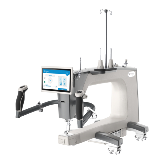
Machine Layout Quilting Machine (Side View) 1. Hand Wheel 2. Thread Mast (page 10) Raises and lowers the needle bar. Guides thread when quilting. 2. Bobbin Thread Tensioner (page 14) 1. Top Thread Stand (page 11) Tensions thread when winding a bobbin. Holds a thread cone for threading machine. - Page 7 Machine Layout (continued) 4. Handlebar Controls (page 17) Handle Bar Clamp (page 17) Controls machine functions. Used to adjust handlebar position. • Tensioner Check Spring (page 32) 6. Handle Bar Levers (page 17) Applies additional tension to thread. Used to adjust handle position. •...
-
Page 8: Ports And Plugins
Ports and Plugins Machine Rear (Underside View) Power On/Off Switch USB Connector Port (page 71) Turns machine on and off. For updating only. Upper Encoder Port (page 54) Power Port with Retainer (page 16) Connects encoders to machine. Connects and holds power cord to the machine. - Page 9 Ports and Plugins (continued) Machine Front Display Cable Port (page 12) Connects display cable to machine. Machine Throat Accessory Ports For laser accessory. Left Handlebar Port (page 17) Plug the left handlebar cable into the machine. Right Handlebar Port (page 17) Plug the right handlebar cable into the machine.
-
Page 10: Oiling And Cleaning
19X Service Manual Oiling and Cleaning Parts & Tools Needed: • Compressed Air Can (optional; not included) Oil Bottle Lint Brush (Tools Box) Note: Use Lubriplate FMO series oil ® (or similar clear mineral oil). Instructions Oil and Clean: • At the start of a new project •... - Page 11 19X Service Manual Oiling and Cleaning (continued) 1. Clear debris from the spring and discs of the 7. In and around the hook assembly, clear small thread tensioner. away any lint, cloth, and thread remnants. Hook Assembly Small Thread Tensioner 2.
- Page 12 19X Service Manual Oiling and Cleaning (continued) Unplug the display cable from the port on 1. Power up the machine. Run the machine in the machine. manual or cruise stitching modes without a bobbin installed for about 10 seconds. This will distribute the oil in the hook assembly without getting oil on your bobbin thread.
-
Page 13: Choosing Your Needle
19X Service Manual Choosing Your Needle Using the wrong type of needle, or using a needle that is bent, broken, or blunt, can damage the fabric, the machine, and needle. For best results: • Use the recommended needle style for your machine (see below). •... - Page 14 19X Service Manual Choosing Your Needle (continued) Needle Diagram Needle Side View Needle Front View Shank Shaft Groove Scarf Point • Shank: Where the needle bar grasps the needle. • Shaft: The long, narrow part of the needle. Needle size is based upon the diameter of the needle shaft.
-
Page 15: Changing The Needle
19X Service Manual Changing the Needle For information on selecting a needle, see page 4. Parts & Tools Needed: Needle Needle Magnet Instructions A broken, bent, or burred needle may break thread, damage fabric, or even damage the machine. Always check that the needle is in good repair before starting a new project, and replace the needle after eight hours of use. - Page 16 19X Service Manual Changing the Needle (continued) 5. Insert the new needle all the way into the 8. Hand-tighten the thumb screw. Do needle bar. Check the needle bar sight not over-tighten if using the fl at-head hole above the thumb screw to make sure screwdriver.
-
Page 17: Changing The Hopping Foot
19X Service Manual Changing the Hopping Foot Removal Instructions To remove the hopping foot for maintenance or to adjust the hopping foot angle, take the following steps: 1. Power off the machine. 2. With the hand wheel, raise the needle so it clears the hoop part of the hopping foot. 3. - Page 18 19X Service Manual Changing the Hopping Foot (continued) Installation Instructions To install the hopping foot on your quilting machine, please take the following steps: 1. Power off the machine. 2. Slide the slot in the hopping foot onto the hopping foot collar. Use the 3 mm Allen wrench and hopping foot screw to hold the hopping foot in place, but do not tighten.
-
Page 19: Replacing The Thread Mast
19X Service Manual Replacing the Thread Mast Parts & Tools Needed: T-handle Allen Thread Mast Wrench 2.5 mm SMP-09-14103 Instructions Take the following steps to replace the thread mast without replacing the entire thread stand: • Use a 2.5 mm Allen wrench to remove the •... -
Page 20: Replacing The Thread Stand
19X Service Manual Replacing the Thread Stand Parts & Tools Needed: T-handle Allen Thread Stand Assembly Wrench 2.5 mm SMP-09-13183 Instructions Take the following steps to replace the thread stand assembly: • Use the 2.5 mm Allen wrench to remove the two M4 x 8 mm SBHCS screws and remove the old thread stand assembly from the right side of the machine. -
Page 21: Replacing The Display
19X Service Manual Replacing the Display Parts & Tools Needed: T-handle Allen T-handle Allen 2.4-Inch Touch Display Display Cable Wrench 3 mm Wrench 2.5 mm SMP-02-15727 SMP-09-15716 Instructions Take the following steps to replace the display: 1. Turn off the machine and unplug the 1. - Page 22 19X Service Manual Replacing the Display (continued) 1. Re-attach the plastic cover with the 2.5 mm Allen wrench. 2. Plug the display cable back into the port behind the display. Display Cable...
-
Page 23: Replacing The Bobbin Winder System
19X Service Manual Replacing the Bobbin Winder System Parts & Tools Needed: T-handle Allen Bobbin Winder System Wrench 2.5 mm SMP-09-16394 Instructions Take the following steps to replace the bobbin winder: 1. Use the 2.5 mm Allen wrench to remove the 1. - Page 24 19X Service Manual Replacing the Bobbin Winder System (continued) 1. Place the new bobbin winder system onto the back of the machine so that the cable goes through the groove behind the motor. New Bobbin Winder System Groove 1. Use the 2.5 mm Allen wrench to secure the bobbin winder system in place with the three screws that were removed earlier.
-
Page 25: Replacing The Power Cord Retainer
19X Service Manual Replacing the Power Cord Retainer Parts & Tools Needed: Power Cord Retainer SMP-08-14475 Instructions Take the following steps to replace the power cord retainer: 1. Turn off the machine and then lift the power 1. Install the new retainer by squeezing the cable retainer (blue) and unplug the power sides and inserting the ends into the retainer cord from the machine. -
Page 26: Replacing The Handlebars
19X Service Manual Replacing the Handlebars Parts & Tools Needed: T-handle Allen Handlebar Assembly Wrench 4 mm SMP-08-14066 Instructions Take the following steps to replace the handlebars: • Turn off the machine and unplug the • Remove the handlebars from machine. handlebar cables. - Page 27 19X Service Manual Replacing the Handlebars (continued) 2. Close the cover and loosely screw in the 4. Twist the controls until they are comfortable cover screw. to hold and operate. 1. Hold the handlebars at the desired angle 1. If desired, extend the handles outward to and tighten the clamp screw.
- Page 28 19X Service Manual Replacing the Handlebars (continued) 2. Plug the handlebar cables into the ports with the matching color. Handlebar Cables...
-
Page 29: Replacing The Led Lamp
19X Service Manual Replacing the LED Lamp To avoid damaging the LED Lamp Parts & Tools Needed: Assembly, keep it in the packaging until you are ready to install it. T-handle Allen L-shaped Allen L-shaped Allen LED Lamp Assembly Wrench 3 mm Wrench 2.5 mm Wrench 2 mm SMP-09-14863... - Page 30 19X Service Manual Replacing the LED Lamp (continued) • Use the 2.5 mm Allen wrench to remove the • Use the 2 mm Allen wrench to remove the screw holding the thread cutter to side two smaller screws on the back of the LED of the machine.
- Page 31 19X Service Manual Replacing the LED Lamp (continued) • Plug the cables into the new LED lamp • Assemble the thread guide with the assembly. spacer next to the wire that points up and then place the screw through the spacer. Spacer New LED Lamp Assembly...
- Page 32 19X Service Manual Replacing the LED Lamp (continued) • Return the hopping foot collar to the press 1. Replace the needle (see “Changing the bar with the mounting bar in the back. Needle” on page 6 for installation instructions). Press Bar Mounting Bar •...
-
Page 33: Replacing The Front Display Board
19X Service Manual Replacing the Front Display Board To avoid damaging the front display Parts & Tools Needed: board circuitry, keep it in the packaging until you are ready to install it. Phillip’s Head Front Display Board Screwdriver SMP-02-16027 Instructions Take the following steps to replace the front display board: Tilt the display back and unplug the bottom Use the Phillip’s head screwdriver to remove... - Page 34 19X Service Manual Replacing the Front Display Board (continued) • Plug the cable into the back of the new 1. Plug the display back into the machine and front display board. adjust the display to a comfortable angle. Cable New Front Display Board Display Cable Use the Phillip’s head screwdriver and the...
-
Page 35: Replacing The Motor Driver Board
19X Service Manual Replacing the Motor Driver Board To avoid damaging the motor driver Parts & Tools Needed: board circuitry, keep it in the packaging until you are ready to install it. T-handle Allen T-handle Allen Motor Driver Wrench 2.5 mm Wrench 2 mm Board SMP-09-14161... - Page 36 19X Service Manual Replacing the Motor Driver Board (continued) Use the 2 mm Allen wrench to secure the Use the 2.5 mm Allen wrench to reattach the middle plastic cover. new motor driver board with the three screws. Middle Plastic New Motor Cover Driver Board...
-
Page 37: Replacing The Main Board
19X Service Manual Replacing the Main Board To avoid damaging the main board Parts & Tools Needed: circuitry, keep it in the packaging until you are ready to install it. T-handle Allen Main Board Assembly Wrench 2.5 mm SMP-09-14303 Instructions Take the following steps to replace the main board: Power off the machine and unplug the Use the 2.5 mm Allen wrench to remove the... - Page 38 19X Service Manual Replacing the Main Board (continued) 1. Secure the new main board assembly in place using the two screws you removed earlier and the the 2.5 mm Allen wrench. New Main Board Assembly 1. Plug the encoders back into the encoder ports with the matching sticker color. Note: If you have QuiltMotion installed, plug the 6P/6C QuiltMotion cable back in as well.
-
Page 39: Replacing The Small Thread Tensioner
19X Service Manual Replacing the Small Thread Tensioner Parts & Tools Needed: T-handle Allen T-handle Allen Small Tensioner Wrench 2.5 mm Wrench 2 mm SMP-08-10015 Instructions Take the following steps to replace the small thread tensioner: 1. Use the 2.5 mm Allen wrench to remove the front display cover from the top of the machine. Front Display Cover 1. - Page 40 19X Service Manual Replacing the Small Tensioner (continued) 1. Place the new small thread tensioner in the front display cover with one thread guide pointing down and the other pointing up and to the right. New Small Tensioner 1. Tighten the clamp over the small thread tensioner using the 2 mm Allen wrench 1.
-
Page 41: Replacing The Large Thread Tensioner
19X Service Manual Replacing the Large Thread Tensioner Parts & Tools Needed: Small Flat-Head T-handle Allen Large Tensioner Screwdriver Wrench 3 mm SMP-09-13180 Removal Instructions Take the following steps to remove the large thread tensioner from the machine: Use a 3 mm Allen wrench to loosen the set screw holding the large thread tensioner in place. - Page 42 19X Service Manual Replacing the Large Thread Tensioner (continued) Reassembly Instructions If your tensioner has fallen apart, take the following steps to reassemble the pieces: Place the tension discs on the thread Place the tensioner spring on the tensioner post. Place the discs so the tensioner post with the top end of the curved sides face each other.
- Page 43 19X Service Manual Replacing the Large Thread Tensioner (continued) Installation Instructions Take the following steps to install the thread tensioner to your machine: Insert the tensioner into the side of the machine with the check spring coming out of the tensioner at a 45 degree angle to the ground.
- Page 44 19X Service Manual Replacing the Large Thread Tensioner (continued) Turn the screwdriver clockwise until the check spring stops moving and then continue turning another 90 degrees. The check spring should still be at about a 45 degree angle to the ground.
-
Page 45: Replacing The Thread Cutter
19X Service Manual Replacing the Thread Cutter Parts & Tools Needed: T-handle Allen Thread Cutter Wrench 2.5 mm SMP-04-12082 Instructions Take the following steps to replace the thread cutter over the needle area: • Use the 2.5 mm Allen wrench to remove the screw holding the old thread cutter to side of the machine. -
Page 46: Checking The Thread Guides
If you feel damage the previous step. Feel for any snagging or to one of these thread guides, contact The rough sections. Grace Company or your local dealer. - Page 47 19X Service Manual Checking the Thread Guides (continued) If you feel damage to the thread mast guide loops, you will need to replace the thread mast. See instructions for “Replacing the Thread Mast” on page 10. Thread Mast Guide Loops If you feel damage to the guides that are part of the tensioner assemblies, you will need to replace the damaged part.
- Page 48 19X Service Manual Checking the Thread Guides (continued) • To change the bottom thread guide, use the 2.5 mm Allen wrench to remove the screw holding the thread guide and spacer to the LED lamp. Spacer Screw Thread Guide • Assemble the thread guide with the spacer next to the wire that points up and then place the screw through the spacer.
-
Page 49: Replacing The Needle Bar Thread Guide
19X Service Manual Replacing the Needle Bar Thread Guide Parts & Tools Needed: Flat-head Needle Bar T-handle Allen Large Screwdriver Screwdriver Thread Guide Wrench 3 mm SMP-04-10039 Instructions Take the following steps to replace the needle bar thread guide: 1. Power off the machine. Raise the needle to •... - Page 50 19X Service Manual Replacing the Needle Bar Thread Guide (continued) Place the new thread guide onto the end of • See “Changing the Needle” on page 6 for the needle bar with guide hole facing the instructions on reinstalling the needle. front.
-
Page 51: Replacing The Bobbin Springs
19X Service Manual Replacing the Bobbin Case Springs Parts & Tools Needed: Small Bobbin Large Bobbin Thread Tension Spring Anti-Backlash Spring Case Screw Case Screw SMP-03-13101 SMP-03-13102 SMP-03-13103 SMP-03-13104 Small Flat-Head Screwdriver Tension Spring Instructions Take the following steps to replace the tension spring on the bobbin case: Use the small flat-head screwdriver to remove the two screws holding the thread tension spring to the outside of the bobbin case. - Page 52 19X Service Manual Replacing the Bobbin Case Springs (continued) Place the new tension spring on the side of the bobbin case with the tabs going in the slots near the hinge for the lever. Tabs New Tension Spring Use the small flat-head screwdriver to attach the spring to the bobbin case with the small bobbin case screw in the screw hole at the end of the spring.
- Page 53 19X Service Manual Replacing the Bobbin Case Springs (continued) Anti-Backlash Spring Instructions Take the following steps to replace the anti-backlash spring in the bobbin case: Lay the bobbin case face-down so that the opening is facing up. Position the anti-backlash spring so that the center section is raised above the outside of the spring.
- Page 54 19X Service Manual Replacing the Bobbin Case Springs (continued) Press the other side of the spring down and insert the other tabs on the other side. Use the small flat-head screwdriver to make sure all four tabs are fully secured. Place the bobbin in the bobbin case.
- Page 55 19X Service Manual Troubleshooting the Encoders Instructions There is a variety of encoder issues that could cause issues with your stitching. Take the following steps to determine if and how the encoders are not functioning correctly: Try sewing in manual mode to see if the issue continues. This quilting mode is unregulated and does not use the encoders.
- Page 56 19X Service Manual Troubleshooting the Encoders (continued) Press the button on the display to start stitching in precise mode. Lift the encoder wheel off the tracks and spin it by hand and observe the needle. If the needle moves normally, check the encoder spring and lock collar and replace if needed.
- Page 57 19X Service Manual Troubleshooting the Encoders (continued) If both sides click into place, try stitching again to see if the issue continues. If it does continue, try swapping the upper and lower encoder cables and try stitching again. If the issue switches directions (for example, it was making long stitches going front to back but now makes long stitches going left to right) the cable will need to be replaced.
-
Page 58: Replacing The Encoder Spring
19X Service Manual Replacing the Encoder Spring Parts & Tools Needed: T-handle Allen T-handle Allen Upper Encoder Lower Encoder Wrench 2.5 mm Wrench 4 mm Spring (Silver) Spring (Black) HDW-03-10216 HDW-03-10671 Instructions If the encoder spring is over-tensioned, it may break and need to be replaced. To replace the encoder spring, take the following steps: 3. - Page 59 19X Service Manual Replacing the Encoder Spring (continued) 1. Remove the plastic stop, wheel spacer, washer, broken encoder spring, and shoulder spacer from the encoder. Plastic Shoulder Stop Spacer Wheel Spacer Encoder Washer Spring 2. Pull on the lock collar to remove it from the 4.
- Page 60 19X Service Manual Replacing the Encoder Spring (continued) Adjust the screw and lock collar so the head 1. Complete the installation instructions for the of the screw slides in between the lock encoder you repaired. collar. For the upper encoder (silver spring) installation instructions, see page 52.
-
Page 61: Replacing The Upper Encoder
19X Service Manual Replacing the Upper Encoder Parts & Tools Needed: T-handle Allen T-handle Allen Upper Encoder Wrench 4 mm Wrench 2.5 mm (silver spring) SMP-09-10668 Instructions Take the following steps to replace your upper encoder: Unplug the encoder from the machine Remove the wheel from the old encoder. - Page 62 19X Service Manual Replacing the Upper Encoder (continued) 1. Place the encoder screw into the left rear 4. Plug the upper encoder cable into the wheel hole so the dark encoder wheel is purple encoder port on the back left of between the two left machine wheels.
-
Page 63: Replacing The Lower Encoder
19X Service Manual Replacing the Lower Encoder Parts & Tools Needed: T-handle Allen T-handle Allen Lower Encoder Wrench 4 mm Wrench 2.5 mm (black spring) SMP-09-13427 Instructions Take the following steps to replace your lower encoder: Unplug the encoder from the green Remove the wheel from the old encoder. - Page 64 19X Service Manual Replacing the Lower Encoder (continued) 1. Place the encoder screw into the left rear To plug in the lower encoder, take the free wheel hole on the carriage so the encoder end of encoder cable (shown in blue) and wheel is between the rear wheels.
-
Page 65: Replacing A Machine Wheel
19X Service Manual Replacing a Machine Wheel Parts & Tools Needed: Wheel Bearing Allen Wrench 4 mm HDW-03-10126 Instructions Take the following steps to replace a machine wheel: Use the 4 mm Allen wrench to remove the old wheel and the wheel screw. Note: If you are replacing an inside wheel and have QuiltMotion installed on your machine, you may need to... - Page 66 19X Service Manual Replacing a Machine Wheel (continued) If you are replacing a wheel without the machine channel lock or upper encoder, use the 4 mm Allen wrench and the wheel screw to install the new wheel. New Wheel Wheel Screw If you are replacing a wheel with the machine channel lock or the upper encoder, see your user manual for installation instructions.
-
Page 67: Replacing The Hand Wheel
19X Service Manual Replacing the Hand Wheel Parts & Tools Needed: T-handle Allen Hand Wheel Wrench 4 mm SMP-05-10026 Instructions Take the following steps to replace your hand wheel: Use the 4 mm Allen wrench to remove the Secure the hand wheel in place with the old hand wheel and the connector bolt connector bolt and the 4 mm Allen connecting the hand wheel to the machine. -
Page 68: Reinstalling The Needle Plate
19X Service Manual Reinstalling the Needle Plate Parts & Tools Needed: Flat-head Screwdriver Removal Instructions To remove the needle plate from the quilting machine, take the following steps: 1. Power off the machine and raise the needle to the highest position using the hand wheel. 2. - Page 69 19X Service Manual Reinstalling the Needle Plate (continued) Installation Instructions To install the needle plate onto the quilting machine, take the following steps: 1. Power off the machine. Raise the needle to 4. Place the two needle plate screws (shown the highest position using the hand wheel.
-
Page 70: Timing The Machine
Timing your machine aligns the needle and hook assembly so that they are in the correct places during the creation of a stitch. Improper timing can result in damage to the machine and needle, or make sewing impossible. Please consult with a Grace Company support technician before attempting to adjust the timing on your machine. - Page 71 19X Service Manual Timing the Machine (continued) 5. As each of the 3 set screws aligns with the 8. Stop raising the needle once the eye is about level with the hook (shown in blue). Do not timing cut-out, loosen them with the 2 mm Allen wrench.
- Page 72 19X Service Manual Timing the Machine (continued) Position the tip of the hook (shown in blue) with the center of the Needle Scarf (shown in gray). This is easier to see from the back of the machine. Pull the hook assembly toward the front of Use the 2 mm Allen wrench to tighten one the machine until the hook is as close to the of the three set screws through the timing...
- Page 73 19X Service Manual Timing the Machine (continued) Turn the timing spacer tool until the fl at side is facing up and then remove it from the machine. Turn the hand wheel a full rotation to listen for clicking noises and to ensure the needle does not bend or hit the hook Tighten the two remaining set screws through the timing cut-out.
-
Page 74: Replacing The Hook Holder
The hook holder keeps the hook assembly in place. The following procedure should only be attempted if determined necessary by a Grace Company support technician. If done incorrectly, major machine problems can result. Please call (800) 264-0644 before attempting this procedure. - Page 75 19X Service Manual Replacing the Hook Holder (continued) Installation Instructions 5. Turn the inside part of the hook assembly 1. Turn off the machine. (shown in blue) so that the positioning guide is at the highest point. 2. Rotate the hand wheel to raise the needle to the highest point.
- Page 76 19X Service Manual Replacing the Hook Holder (continued) Align the hook holder (blue) with the inside edge of the positioning guide (gray) as shown below. Tighten the hook holder screw to fasten the hook holder in place. The inside part of the hook assembly should no longer rotate freely by hand.
-
Page 77: Updating Display Firmware
19X Service Manual Updating Display Firmware Parts & Tools Needed: Desktop or Laptop Mini USB cable Computer Use a desktop or laptop computer to download the update and the DfuSe Demo app zip fi le that were sent to your email. Note: If you have already installed the DfuSe Update DfuSe Demo... - Page 78 19X Service Manual Updating Display Firmware (continued) A new window will pop up with the now Select Install. opened zip fi le. Select the fi le named DfuSe_Demo_V3.0.6_Setup again. Select Next. Select Finish. Select Next again. You do not need to fi ll Plug a mini USB cable into your computer out User Name or Organization.
- Page 79 19X Service Manual Updating Display Firmware (continued) Select Yes. Open the DfuSe Demo program. Select Choose in the Upgrade or Verify Action section and then select the upgrade fi le you downloaded earlier. Note: If the machine is not properly connected to your computer, this...
-
Page 80: Updating Machine Firmware
19X Service Manual Updating Machine Firmware Parts & Tools Needed: Desktop or Laptop Mini USB cable Computer Instructions Take the following steps to update the display fi rmware: Use a desktop or laptop computer to download the update and the DfuSe Demo app zip fi le that were sent to your email. - Page 81 19X Service Manual Updating Machine Firmware (continued) Select Install. A new window will pop up with the now opened zip fi le. Select the fi le named DfuSe_Demo_V3.0.6_Setup again. Select Next. Select Finish. Select Next again. You do not need to fi ll Use the power switch on the back of the out User Name or Organization.
- Page 82 19X Service Manual Updating Machine Firmware (continued) Unplug the display cable. Check the box labeled Verify after download. Display Cable Plug a mini USB cable into your computer Select Upgrade. and then plug the other end into the USB connector port on the rear of the machine. USB Connector Port Open the DfuSe Demo program.
- Page 83 19X Service Manual Updating Machine Firmware (continued) After the update is complete, close the app on your computer and unplug the mini USB from the USB connector port in back of the machine. USB Connector Port Plug in the display cable. Display Cable Turn the machine on with the power After updating the machine fi rmware,...
-
Page 84: Calibrating The Machine Speed
19X Service Manual Calibrating the Machine Speed Instructions The self speed calibration is used to ensure that your machine is running at the correct speed. Each machine has already been calibrated and set at the factory and doesn’t need to be changed regularly. Only run self speed calibration if you have recently updated your software and are having issues with your stitch regulation, baste, or your machine is running slow. - Page 85 19X Service Manual Calibrating the Machine Speed (continued) 1. Tap three times on the blank space underneath the back arrow on the System Info screen to open the testing menu. Tap here three times. #X## XX/XX/XX ##X## XX/XX/XX 1. Select Calibration to open the Self Calibration screen. XXXX XXXX 1.
-
Page 86: Window Offset
You can address this issue by adjusting the window off set, which changes the position of the needle stop. Only do this if a Grace Company technician advises you to do so. Take the following steps to access the testing menu and adjust the window off set: 1. - Page 87 19X Service Manual Window Off set (continued) 1. Select Calibration to open the Self Calibration screen. XXXX XXXX 1. Press the needle button to prepare the window off set to be adjusted. Then use the up and down buttons on the left handlebar to increase or decrease the window off set. Needle Button XXXX XXXX...
- Page 88 19X Service Manual Encoder Test Instructions If you are concerned that your encoders are not functioning properly, you can use the encoder test in the testing menu to make sure the encoders are connected and correctly sending signals to your machine.
-
Page 89: Measure Encoder Test
19X Service Manual Measure Encoder Test (continued) 1. Tap three times on the blank space underneath the back arrow on the System Info screen to open the testing menu. Tap here three times. #X## XX/XX/XX ##X## XX/XX/XX 1. Select Encoder Test to open the Encoder Test screen. 1. - Page 90 19X Service Manual Measure Encoder Test (continued) 1. Now move your machine forward and backward on your bottom carriage. The upper encoder should register movement along the carriage’s tracks, also called the “Y-axis” of your frame. If the encoder is correctly signaling this movement to your machine, the “Y” on your display will turn green.
-
Page 91: Button Test
19X Service Manual Button Test Instructions Take the following steps to access the testing menu and perform a button test to make sure your handlebar buttons are functioning correctly: 1. Open the settings menu and press the info button to access the System Info screen. Info Button 1. - Page 92 19X Service Manual Button Test (continued) 1. Select Button Test and the button test screen will appear. 1. Press the buttons on your handlebars one at a time. The corresponding buttons on the button test screen will turn green if the buttons are working correctly.
-
Page 93: Needle Sensor Test
19X Service Manual Needle Sensor Test Instructions Your machine is equipped with an optical sensor that tells the machine’s computer if the needle is in the correct position and if it is moving at the correct speed. Take the following steps to access the testing menu and perform a test to make sure this sensor is working properly: 1. - Page 94 19X Service Manual Needle Sensor Test (continued) 1. Select Sensor Test and the sensor test screen will appear. 1. Rotate the hand wheel counter-clockwise on your machine. Hand Wheel The motion light should turn green as you turn the hand wheel. The Needle Up and Needle Down lights should alternate so that the Needle Up light turns green when the needle is about halfway up to its highest position and the Needle Down light turns green when the needle is about halfway back down to its lowest position.
-
Page 95: Index
19X Service Manual Index Symbols 7 inch touch display ..........12 lamp ..............vi, 20 large bobbin case screw ........... 43 large tensioner ............32 layout ............... v anti-backlash spring ..........44 lint brush ..............1 lower encoder ............51 bobbin case ............ - Page 96 19X Service Manual Index (continued) tension discs ............33 tensioner spring ............33 tension meter ............33 test encoders ............76 testing menu .......... 72, 74, 80, 82 thread guides ............37 thread mast ............10 thread mast loops ............ 38 thread stand ............
- Page 97 Information on the disposal for Waste Electrical & Electronic Equipment (WEEE): This symbol on the products and accompanying documents means that used electrical and electronic products should not be mixed with general household waste. For proper disposal for treatment, recovery and recycling, please take these products to designated collection points where they will be accepted on a free-of-charge basis.
- Page 98 The Grace Company Phone: 1-800-264-0644 www.graceframe.com...
Need help?
Do you have a question about the Q'nique 19 X and is the answer not in the manual?
Questions and answers
HOW OFTEN TO CHANGE NEEDLE ON QNIQUE 19X
ho do i remove the needle bar from a qnique 19
I went to place my pattern and it only showed half pattern