Table of Contents
Advertisement
Quick Links
Advertisement
Table of Contents

Related Manuals for Comelit 1404


Summary of Contents for Comelit 1404
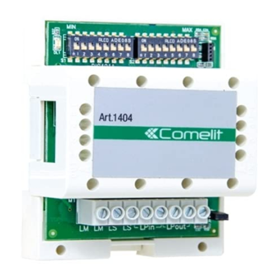
- Page 1 TECHNICAL MANUAL Ar 1404 LM LS LS LPin LPout MYCOMELIT: THE APP FOR PROFESSIONALS MYCOMELIT, L'APP PER IL PROFESSIONISTA FREE DOWNLOAD Digital switching device for Simplebus 2 system Art. 1404...
-
Page 2: Table Of Contents
• any purpose other than the intended use, • failure to observe the indications and warnings contained in this Manual / Instruction sheet. Comelit Group S.p.A. reserves the right to change the information provided in this Manual / Instruction Sheet at any time and without prior notice. -
Page 3: Description
Description Product number 1404 is an audio/video switching device for use in Simplebus 2 systems. To be used in systems with more than one entrance. LM LS LPin LPout 1. DL1 indicator LED off: switching device on secondary external unit steadily lit: switching device on main external unit flashing: LP line missing or short-circuited/reset (only with R.I. -
Page 4: Connections
Connections 1404 connections RISER BUS LINE MAIN BUS LINE OUTPUT OUTPUT 1404 SECONDARY BUS DIP 4 LINE INPUT (S3) POWER SUPPLY DIP 4 INPUT (S3) MAIN BUS LINE OUTPUT... -
Page 5: Operation And Programming
Operation and Programming Switching device Art. 1404 includes 3 operating modes; the mode should be selected based on the type and position of the switching device in that same system: STANDARD (for use in systems which require the addition of extra external units) -
Page 6: Examples
Only external units in TOP mode can be wired to the TOP 3 switching device. Self activation CANNOT be managed via wired ports on the LPin-LPin input of switching device Art. 1404. CAUTION! Separate switching devices must manage code ranges which are not overlapping. -
Page 7: Programming Table For Dip-Switches And S3 Setting
Programming table for dip-switches and S3 setting User code/ DIP SWITCH User code/ DIP SWITCH User code/ DIP SWITCH User code/ DIP SWITCH zone zone zone zone 1 2 3 4 1 2 3 4 1 2 3 4 1 2 3 4 1 2 3 4 1 2 3 4 1 2 3 4... -
Page 8: Technical Specifications
Technical specifications GENERAL FEATURES Input connector Terminal block CE certification EMC 2014/30/EU (EN 61000-6-1:2007, EN 61000-6- 3:2007+A1:2011) MAIN FEATURES Height (mm) Width (mm) Depth (mm) Product weight (g) Operating temperature (°C) -10 to 40 Operating humidity (max. RH) (%) 25 to 95 DIN rail mounting DIN modules (no.) Power supply voltage (V) -
Page 9: System Performance And Layouts
System performance and layouts Single-family KIT: with switching devices in STANDARD mode and 2 inputs 1 2 3 4 1 2 3 4 1404 1 2 3 4 1 2 3 4 1 2 3 4 110-240V 110-240V 1209 1209... - Page 10 Single-family KIT: with switching devices in STANDARD mode and 3 inputs 1 2 3 4 1 2 3 4 1404 1404 1 2 3 4 1 2 3 4 1 2 3 4 1 2 3 4 1 2 3 4...
- Page 11 6750W 1214/2C 6701W 6741W 6701W/BM 6721W 6741W/BM 6721W/BM 6701W/8 1214/2C 6601W/ 6601W/BM 1214/2C 1404 1 2 3 4 1 2 3 4 1 2 3 4 230V 230V 1210 1210 1210A 1210A R GND R GND NO NC NO NC...
- Page 12 6741W/BM 6721W/BM 6701W/8 1214/2C 1214/2C 6601W/ 6601W/BM 6601W/ 6601W/BM 1214/2C 1214/2C 1404 1404 1 2 3 4 1 2 3 4 1 2 3 4 1 2 3 4 1 2 3 4 1 2 3 4 230V 230V 230V...
- Page 13 1 2 3 4 6 7 1 2 3 4 6 7 ZONA 3 ZONA 4 TOP 1 1404 TOP 1 1404 1 2 3 4 6 7 1 2 3 4 6 7 1 2 3 4 6 7...
- Page 14 System with art. 4888C: switching devices in TOP1 mode, 2 branched KITs, and KITs in cascade 6801W/ 6801W/BM 1 2 3 4 1 2 3 4 ZONA 2 TOP 1 1404 1 2 3 4 1 2 3 4 1 2 3 4 110-240V 1209 1216 1214/2C...
- Page 15 1 2 3 4 1 2 3 4 1 2 3 4 1 2 3 4 1 2 3 4 1 2 3 4 1404 1404 1404 1 2 3 4 1 2 3 4 1 2 3 4 1 2 3 4...
- Page 16 System with art. 1210/1210A: switching devices in TOP1 and TOP3 mode, 2 main external units and n secondary external units TOP 1 1404 TOP 1 1 2 3 4 1 2 3 4 1 2 3 4 230V 1210 1210A...
- Page 17 TOP 1 1404 TOP 1 1404 TOP 1 TOP 1 1 2 3 4 1 2 3 4 1 2 3 4 1 2 3 4 1 2 3 4 1 2 3 4 1209 L1 L1 L2 L2 230V...
- Page 18 C E R T I F I E D M A N A G E M E N T S Y S T E M S w w w . c o m e l i t g r o u p . c o m Via Don Arrigoni, 5 - 24020 Rovetta (BG) - Italie...
Need help?
Do you have a question about the 1404 and is the answer not in the manual?
Questions and answers