
Subscribe to Our Youtube Channel
Related Manuals for Lincoln Electric Vernon Tool MasterPipe Compact Profiler


Summary of Contents for Lincoln Electric Vernon Tool MasterPipe Compact Profiler
- Page 1 Vernon Tool® MasterPipe® Compact Pro ler OPERATORS GUIDE Nov 1, 2022 Copyright 2022 Lincoln Electric® Cutting Systems...
-
Page 2: Table Of Contents
Grounding Your Machine .................5 Connect Air Supply ...................6 FlexCut 80 Plasma Controls & Settings ..........7 Overview of Visual Machine Designer ............9 WinMPM Operation ................19 Performing a Test Cut ................25 Maintenance ....................31 Vernon Tool MasterPipe Compact Profiler Page ii... -
Page 3: Machine Specifications
PypeServer (optional) • 1” OD to 8” OD (25.4 - 203.2mm)* 1” pipe requires Motion Controller additional support cradle • Lincoln Electric Accumove Controller • 100 lb (45.3 kg) per foot • 1000 lb (453.6 kg) maximum tube weight •... -
Page 4: Safety Information
Safety Information Torchmate and Lincoln Electric Cutting Systems equipment is designed and built with safety in mind. However, your overall safety can be increased by proper installation and thoughtful operation. WARNING: DO NOT INSTALL, OPERATE, OR REPAIR THIS EQUIPMENT WITHOUT READING THE SAFETY WARNINGS CONTAINED THROUGHOUT THIS MANUAL. - Page 5 FUMES AND GASES can be dangerous: Plasma cutting or gouging may produce fumes and gases hazardous to health. Avoid breathing these fumes and gases. When cutting or gouging, keep your head out of the fumes. Use adequate ventilation and/or exhaust at the arc to keep fumes and gases away from the breathing zone. Use an air-supplied respirator if ventilation is not adequate to remove all fumes and gases.
- Page 6 Cutting flame and sparks can cause FIRE OR EXPLOSION: • Fire and explosion can be caused by hot slag, sparks, oxygen fueled cutting flame, or the plasma arc. • Have a fire extinguisher readily available. Provide a fire watch when working in an area where fire hazards may exist.
- Page 7 ARC RAYS CAN BURN: • Plasma Arc Rays can injure your eyes and burn your skin. The plasma arc process produces very bright ultraviolet and infrared rays, which will damage your eyes and burn your skin if you are not properly protected.
- Page 8 AUTOMATIC OPERATION: • Any computer numerical control (CNC) machine may begin to operate automatically without warning. Only a trained individual familiar with the software, machine, and computer system should operate this equipment. • All untrained persons should not work on or near a CNC machine. •...
- Page 9 PUBLICATIONS Refer to the most recent vesrions of the following standards for more information: • OSHA, SAFETY AND HEALTH STANDARDS, 29CFR 1910, obtainable from the Superintendent of Documents, U.S. Government Printing Office, Washington, D.C. • ANSI Standard Z49.1, SAFETY IN WELDING AND CUTTING, obtainable from the American Welding Society, 8669 NW 36 Street, #130;...
-
Page 10: Machine Overview
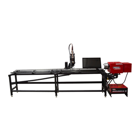
Machine Overview Overview of the Vernon Tool MasterPipe Compact Profiler, the chuckbox and its frequently moving parts. MasterPipe Compact Profiler, Back View Chuck Box Lifter Station Chuck Box adjustment levers Leveling Feet Ball Transfer Cradles Vernon Tool MasterPipe Compact Profiler... - Page 11 Machine Overview: MasterPipe Compact Profiler, Front View Adjustable jaw, rotating chuck Cutting bed Chuck Box adjustment levers Air and Ground connections (inside removable chuck box) User Guide Page 2...
-
Page 12: Power/Air Requirements
Torchmate 4400/4800/4510. The Vernon Tool MasterPipe Compact Profiler machine requires clean, dry, oil-free compressed air or nitrogen. A high pressure regulator MUST be used with a compressor or high pressure cylinder. Supply pressure must be between 87-110 psi (6-7.6 bar) with flow rated rates of at least 300 SCFH or 140 SLPM. - Page 13 Remove the chuck box cover: MasterPipe Compact Profiler is equipped with a rotating ground located under a protective metal cover at the rear of the machine drive assembly. The pneumatic connection for the air ventilation is also located under this cover.
-
Page 14: Grounding Your Machine
With both the work lead and ground wire installed into the rotating ground clamp, tighten the 1/4” hex head bolts until both ground wires are firmly secured. Locate the plastic shield back into the rotating ground capture and reinstall the #2 slotted set screw. Vernon Tool MasterPipe Compact Profiler Page 5... -
Page 15: Connect Air Supply
The machine and plasma cutter requires a supply of dry, oil-free, regulated compressed air. Ensure that you have the have the correct supplies connected to the plasma cutter and that the flow/pressure of the supply falls within the specified ranges. Please see the Lincoln Electric FlexCut 80 user guide for specifications. Connect the air: Instructions: Validate the specifications supplied with your plasma cutter. -
Page 16: Flexcut 80 Plasma Controls & Settings
GAS PRESSURE YELLOW LED PARTS-IN-PLACE (PIP) YELLOW LED OUTPUT CURRENT KNOB CNC INTERFACE WORK GROUND BACK INPUT CORD - 10 ft. (3.0 M) POWER SWITCH AIR OR GAS INLET (1/4 in. NPT QUICK CONNECT) Vernon Tool MasterPipe Compact Profiler Page 7... - Page 17 FlexCut 80 Plasma Controls & Settings Please refer to the FlexCut operators manual for complete installation and operation guidelines. Do not overtighten the consumables. Only tighten until the parts are seated properly. Rated Output: Product Product Input Power Current/ Input Current @ Output Gas Pressure Gas Flow...
-
Page 18: Overview Of Visual Machine Designer
AVHC/Dashboard - Control the AVHC and displays the coordinates of the head along with all of the indicators being monitored on the machine. Accessory Toggle - This hosts the on/off toggle button for the laser pointer accessory. Vernon Tool MasterPipe Compact Profiler Page 9... - Page 19 Job Group The Job Group covers any “job” type functions. This group directly deals with selecting a job, creating a job (Shape Library), Nesting, and other Job type functions. Select Job: Allows the operator to choose the job which they would like to load. The SELECT JOB folder shows the “HOT FOLDER”...
- Page 20 Prompts a dialog box to TURN OFF ACCUMOVE CONTROLLER. • Press the E-Stop button to power down the controller. • The computer will then shut down. • Turn the power switch to OFF. Vernon Tool MasterPipe Compact Profiler Page 11...
- Page 21 View Screen The main view screen of the VMD hosts tabs that control and display the job and the corresponding settings for cutting the material. The tabs at the top of the screen gives the operator different views and controls for the job planning to be cut. Process Setup: The process setup tab is used to enter the material you are planning to cut.
- Page 22 • Trace Pause/Resume - Pauses the graph if tracing. • Trace Off/On - Toggles viewing the lifter station’s movement during operation. • Maximize Viewport - Displays all views in one screen. Vernon Tool MasterPipe Compact Profiler Page 13...
- Page 23 Run Group The Run group controls the startup of the machine along with running jobs. Datum: Datum has several features. When first starting up your machine, datum will power your motors and move the machine to establish its MACHINE ZERO. When pressing DATUM, the Z-AXIS will travel to it’s top zero point.
- Page 24 CUT TO POSITION - Process a ARC ON signal and move the torch to the postion and feedrate defined. • MOVE TO POSTION - Moves the torch to the defined position and feedrate defined. Vernon Tool MasterPipe Compact Profiler Page 15...
- Page 25 AVHC & Dashboard AVHC (Arc Voltage Height Control) hosts “how” the controllelr handles the lifter station. Dashboard gives the operator insight into the head position and other status indicators. AVHC (Automatic Voltage Height Control): Cut Parameters can be toggled between Program Defined and User Defined: •...
- Page 26 OK to Move - Indicates when the plasma has pierced through the material and is ready to start the program. • IHS - Indicates when the material is detected via OHMIC. • Breakaway - Indicates if the breakaway circuit is open/closed. Vernon Tool MasterPipe Compact Profiler Page 17...
- Page 27 User Guide Page 18...
-
Page 28: Winmpm Operation
Open the WinMPM software by swiping from right to left from the right edge of the Step 1: screen, and clicking the WinMPM program on the taskbar. Select the F1. Program button to begin programming a pipe to cut. Step 2: Vernon Tool MasterPipe Compact Profiler Page 19... - Page 29 WinMPM Operations: F1. PROGRAM: The following example will illustrate how to create a program that will cut a 3.5 inch O.D. Schedule 40 pipe with a 45 degree saddle on one end, and a straight cut on the opposite end. The Baseline length will be 5” long between the bottom (ID) of the saddle and the straight cut.
- Page 30 To program the other end of the part, select the F4. End 1 drop down list, and choose a Saddle cut from the list. Step 6: Select the F1. Edit button to access the saddle cut’s parameters. Vernon Tool MasterPipe Compact Profiler Page 21...
- Page 31 WinMPM Operations: Once the F1. EDIT is pressed, the Saddle - Single Intersection diagram displays, input the Step 7: parameters of the saddle cut. For this example, a 45 degree saddle on 3” Schedule 40 pipe is being programmed. Note that as parameters are entered under the End 1 Saddle Cut Data section, the short description underneath will update to match.
- Page 32 The tools at the bottom allows the operator to rotate to visualize the cut. Choosing F7. PRINT CUT SHEET will generate a cut sheet to provide production personnel with information regarding the final pipe product. A printer is required for a cut sheet to be generated. Vernon Tool MasterPipe Compact Profiler Page 23...
- Page 33 WinMPM Operations: Once the G-CODE has been generated, switch over to the Visual Machine Designer to load. To load a cut program, go to the Select Job button. Step 11: Follow the process described in the Performing a Test Cut section of this user guide. By default, WinMPM saves the programmed G-Code to- C:\WinMPM\Torchmate VMD Jobs\ User Guide Page 24...
- Page 34 Vernon Tool MasterPipe Compact Profiler Page 25...
-
Page 35: Performing A Test Cut
Performing a Test Cut The MasterPipe Compact Profiler ships with two factory test cut pieces. The first test cut piece is a 3” Schedule 40 pipe: 45° saddle feature on one end, and a straight cut on the other. The second cut is a 3”... - Page 36 Verify that the “Is Job Kerf Compensated” selection is set to Yes. With the job selected and the “Is Job Kerf Compensated” selection set to Yes, click the OK button to open the job. Vernon Tool MasterPipe Compact Profiler Page 27...
- Page 37 Performing a Test Cut: Setup the job: In the PROCESS SETUP tab: • Set the Material type to Mild Steel • Set the Thickness to .216 • Set the Current to 60 Load a piece of 3” Schedule 40 pipe into the machine at least 12” long. Verify the installed consumables are for 60 or 65 amps (depending on your model FlexCut plasma cutter.) Set the amperage on the FlexCut power supply to match the loaded consumables and the Process Setup tab in the VMD software.
- Page 38 Jog the Y axis in the positive direction until you reach the end of the pipe opposite the chuck. Press the SET PLATE ORIGIN button. This tells the machine where the end of the loaded material is located and where to start the program. 3.500 Vernon Tool MasterPipe Compact Profiler Page 29...
- Page 39 Performing a Test Cut: Setting the Pipe Diameter and Plate Origin: After setting the plate origin, jog the Z axis in the negative direction slowly to bring the torch down to touching, or just above the surface of the material, within 1/32”. Press the Set button next to TOP OF MATERIAL input box.
-
Page 40: Maintenance
Tighten X-Belt Lubricate rotating ground Clean and lubricate Y-Rail assembly and bearings (compressed air) Remove debris from the ball transfer cradles(compressed air) Clean AVHC assembly (compressed air) Clean out cable track (compressed air) Vernon Tool MasterPipe Compact Profiler Page 31... - Page 41 User Guide Page 32...
- Page 42 Lincoln Electric is a responsive manufacturer, but the definition of specifications, and the selection and use of specific products sold by Lincoln Electric is solely within the control of, and remains the sole responsibility of the customer. Many variables beyond the control of Lincoln Electric affect the results obtained in applying these types of fabrication methods and service requirements.
Need help?
Do you have a question about the Vernon Tool MasterPipe Compact Profiler and is the answer not in the manual?
Questions and answers