
Related Manuals for Halma Ampac EV3000

Summary of Contents for Halma Ampac EV3000
- Page 1 Fire detection and evacuation solutions that save lives. EV3000 Emergency Warning & Intercommunications System (2 Wire / S004) Installation & Commissioning MAN1813-9...
-
Page 2: Table Of Contents
MAN1813-9 Contents Non Disclosure Agreement ......................1 Certification Information ......................2 Equipment Manufacturing Details....................2 Purpose ............................. 3 Scope ..........................3 References .......................... 3 4.2.1 EV3000 System Manuals: ....................3 4.2.2 Australian Standards..................... 3 System Overview ......................... 3 System Description ........................4 Emergency Warning System .................... - Page 3 MAN1813-9 8.4.3 Completing the Call by the WIP .................. 14 8.4.4 Completing the Call by the ECP ................... 14 8.4.5 ECP Calling WIP ......................14 8.4.6 ECP To All WIPS (ALL CALL) ..................14 8.4.7 Completing The All Call ....................15 8.4.8 EIS Controlling ECP .....................
- Page 4 MAN1813-9 10.5.3 Field Wiring ......................33 10.6 Warning Sign Driver Board (BRD42WSD) ................ 34 10.7 WIP/EAID Extension Connections ................... 35 10.7.1 Connections ......................35 10.7.2 Field Wiring ......................35 10.8 MECP To SECP Data Connections..................36 10.8.1 Connections ......................36 10.9 CN5 + CN6 Power Supply to Board .................
-
Page 5: Non Disclosure Agreement
MAN1813-9 1 Non Disclosure Agreement This contract has been entered into by the person or company user of this document (hereafter called the Trader) and Ampac Technologies (hereafter called Ampac) 7 Ledgar Rd, Balcatta, WA 6021, Western Australia 6017. Under terms and conditions as specified hereunder. Whereas Ampac and the Trader for their mutual benefit and pursuant to a working relationship which may be established, anticipate that Ampac will disclose in the form of this document, information of a secret, or confidential or proprietary nature (hereinafter collectively referred to as Proprietary... -
Page 6: Certification Information
MAN1813-9 2 Certification Information EV3000 EMERGENCY WARNING AND INTERCOMMUNICATION SYSTEM MANUFACTURED BY: AMPAC Technologies Pty Ltd. 7 LEDGAR RD BALCATTA WA 6017 WESTERN AUSTRALIA PH: 61-8-9201 6100 FAX: 61-8-9201 6101 www.ampac.net DESIGNED TO: AS2220.1-1989 AS1670.4-2004 AS4428.4-2004 SSL CERTIFICATE OF COMPLIANCE NUMBER: AFP - 603 3 Equipment Manufacturing Details JOB / SERIAL NUMBER:... -
Page 7: Purpose
Commissioning. Part 4: Intercommunication Systems for Emergency Purposes. 4.3 System Overview The Ampac EV3000 Emergency Warning and Intercommunication System is a microprocessor-based EWIS system that complies with Australian Standards AS2220.1 and produces Alert and Evacuation signals compliant with AS1670.4... -
Page 8: System Description
MAN1813-9 5 System Description 5.1 Emergency Warning System The EWS subdivides the building into evacuation zones. Each evacuation zone has one or more amplifiers and a number of associated speakers. In sections of a building where the background noise is high, visual warning devices may be used in addition to speakers. Each evacuation zone amplifier may be switched by the system to one of four audio channels. -
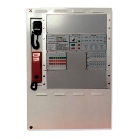
Page 9: Ecp & Main Equipment Layout
MAN1813-9 6 ECP & Main Equipment Layout Figure 1: illustrates a typical EV3000 in a 29U floor standing rack equipped with the main equipment, 24 EWS controls and 48 EIS controls. The standard mechanical construction of the EV3000 is 483mm (19inch) rack mounting frames with EURO Card size plug-in modules. -
Page 10: Ewis Components
MAN1813-9 7 EWIS Components The EWIS is broken into three components: Master Emergency Control Panel Cabling Devices The Master Emergency Control Panels can be further broken down into two sections, Emergency Control Panel Main Equipment 7.1 The Emergency Control Panel The ECP consists of: A Control Panel which contains the Auto/Manual/Isolate facility, the All Call facility, the common System Status and Zone Status controls and indicators. -
Page 11: Ews, Eis And Ecp Operation
MAN1813-9 8 EWS, EIS And ECP Operation The EV3000 ECP has three sections, the; Emergency control panel, EWS control panel; and EIS control panel. 8.1 Emergency Control Panel The Emergency Control Panel contains the common system controls and indicators and the common EWS controls and indicators and the operating instructions. -
Page 12: Automatic / Manual / Isolate Key Switch
MAN1813-9 8.1.2 Automatic / Manual / Isolate Key Switch Automatic Position In the Automatic Position the EWS will enter the programmed evacuation sequence when an alarm signal is received from an FACP or EAID. The switch key is removable only in this position. A green automatic indicator is illuminated when the switch is in the automatic position. -
Page 13: All Call Facility
MAN1813-9 within 1 second. Furthermore the system must be in an inactive state, i.e. fans are not running, no alarms are present etc. In this position the control switches and front panel indicators only function locally, with no zone outputs, i.e. speakers and visual alarm devices being activated. The indicators selected in this position will flash. -
Page 14: Master Reset
MAN1813-9 ➢ amplifier / speaker line fault ➢ visual alarm line fault ➢ alarm system fault (FACP, EAID) ➢ communications fault ➢ system on batteries - if all ECP’s remotely powered ➢ battery fault - if all ECP’s remotely powered ➢... -
Page 15: Zone Status (Fault Diagnostics)
MAN1813-9 Battery Fault The battery voltage drops below the lower limit. Battery Isolated The batteries have been isolated from the charger i.e. fuse is blown or circuit breaker is tripped. Signal Fault The tone generator has failed. Alarm system Isolated The alarm system is isolated. Comms Fault A fault is detected in the loop communications or audio bus. -
Page 16: Ews Zone Control Panel
MAN1813-9 8.2 EWS Zone Control Panel 8.2.1 EWS Zone Control Switches and Indicators Figure 5: EWS Keypad The control switches allow any of the four audio channels (BGM, PA Alert or Evac) to be switched to any of the zones. The Control Switches are inhibited when the EWS is in the AUTOMATIC state. Pressing any of the control switches for an evacuation zone shall automatically cancel the previous selection for that zone, i.e. -
Page 17: Eis Control Panel
MAN1813-9 8.3 EIS Control Panel Figure 6: EIS Keypad 8.3.1 WIP Select Switch (One switch per WIP) - when pressed for the first time will initiate a call to the WIP, or answer a call from a WIP. Pressing the switch a second time will terminate the call to the WIP regardless of who initiated the call. -
Page 18: Eis System Operation
MAN1813-9 8.4 EIS System Operation 8.4.1 WIP Calling ECP The following is the procedure when initiating a call from a WIP to the ECP: 1. Remove the handset from the cradle at the WIP. This will cause the appropriate WIP select indicator to flash at all ECP’s and the WIP call buzzer to sound at all ECP’s. -
Page 19: Completing The All Call
MAN1813-9 4. When any of the WIP handsets are taken off the cradle, a connection is made and the WIP select indicator at the ECP goes steady. Similarly as more WIP handsets are taken off the cradle, their respective select indicators at the ECP go steady. 8.4.7 Completing The All Call Replacing the ECP handset on its cradle i.e.: hanging up, will cancel the ALL CALL operation. - Page 20 MAN1813-9 Once the RPC is connected press the 'PUSH TO TALK' button and speak into the microphone (NOTE a pre-announcement chime sounds when the PTT is pressed). To terminate the selection release the 'PUSH TO TALK' button and press 'ENTER/CLEAR'. Once the PTT is released if no other key is pressed, the RPC will automatically disconnect after 10 seconds.
-
Page 21: Main Equipment Description
MAN1813-9 8.5 Main Equipment Description The MAIN EQUIPMENT consists of the Common Control boards, Main CPU, EIS control cards, Amplifiers, Power Supply and Termination boards. 8.5.1 Common Board Frame The common board frame is the top frame in the ECP and houses the following boards/modules. ➢... -
Page 22: Tone Generator
MAN1813-9 8.5.2 Tone Generator The EV3TG is designed to produce the alert and evacuation tones, play the alert and evac speech messages and produce the test tone for monitoring the operation of the amplifier. Figure 8 BRDEV3TG Tone Generator Board The DIP SWITCH settings are: Function Country Code / Standard... -
Page 23: Standby Tone Generator
MAN1813-9 8.5.3 Standby Tone Generator This board is the STANDBY to the main tone generator board. Should the main board fail, the STANDBY board is automatically switched into circuit and the TONE fault indicator on the front panel is illuminated. 8.5.4 Microphone / BGM Mixer Board The microphone preamplifier board accepts inputs from the Panel MIC via a microphone preamp (302- 475), Remote Paging Console and two BGM Inputs. -
Page 24: Main Cpu
MAN1813-9 8.5.7 Main CPU The Main CPU is responsible for the total control of the EWS and EIS, the communication with other ECP’s, remote paging consoles, FireFinder and houses the program module. The Main CPU has an Address setting that is factory set by way of a dipswitch. It also has another dipswitch which controls the time from alert to evacuation modes whilst in automatic. -
Page 25: 120-Watt Amplifier
MAN1813-9 Figure 11: 40-Watt Amplifier with Heatsink / Cover & Transformer Removed 8.5.10 120-Watt Amplifier The 154-0077 (120W) amplifier option requires two amplifier positions and a minimum line impedance of 83Ω. As in the case of the 40-Watt amplifier the output level can be adjusted by way of RV2 on the front of the 302 5690 card. -
Page 26: Warden Intercom Control Frame
MAN1813-9 STUD1 10 AMP LED3 FAULT LED2 POWER P/S SHUTDOWN LED1 WARNING HIGH VOLTAGE RV1, 2 API-570-D FACTORY SET ON;Y 120 WATT AMPLIFIER DC-DC CONVERTER STUD2 Figure 8: 120 Watt Amplifier DC to DC Converter INDICATORS DC SUPPLY OVERLOAD 302-569 FUSE POWER OUTPUT HEATSINK 10 AMP... -
Page 27: Eis Control Cpu
MAN1813-9 8.5.12 EIS Control CPU This board provides the interface between the EIS selector board and the main CPU. The secondary CPU has an address setting which is factory set and should not be field adjusted. Each CPU services four EIS selector boards, i.e. 16 WIP Extensions. 8.5.13 EIS Selector Board The EIS selector board, BRDEV3EIC3-A, provides the control, audio switching, EAID and ring signal to the WIP extension and services 4 WIP extensions. -
Page 28: Fault Relay
MAN1813-9 RV1 & RV2 ARE FACTORY 1 AMP SINGLE P/S OPERATION SET AND SHOULD NOT INSERT LK1 & REMOVE LK2 BE ADJUSTED DUAL P/S OPERATION INSERT LK1 & LK2 LED1 HIGH V MAINS1 LED2 MAINS2 LED3 POWER LOW V RV3 - WITH THE BATTERY LED4 HIGH V FUSE REMOVED ADJUST... -
Page 29: Installation
MAN1813-9 9 Installation 9.1 Unpacking And Inspection Carefully check packing prior to unpacking goods for any external transit damage. Unpack the goods and check the goods both externally and internally for any loose or damaged components or any problem which may affect the appearance, installation or operation of the goods. Ensure all wiring harnesses are secure, all plugs are correctly fitted into their sockets, each circuit board is secure, and that all fixings and earth studs are tight. -
Page 30: Connecting The Ev3000
MAN1813-9 10 Connecting The EV3000 All the field terminations are accommodated on the back pan of the Main Equipment. 10.1 FACP Input Connections (Individual inputs) The 302-4940 is the Field Connection board for the FACP Inputs. Each board connection terminates sixteen FACP inputs. -
Page 31: Common Facp Input Connections
MAN1813-9 INPUT INPUT INPUT INPUT INPUT COMMON 16 15 14 13 12 11 10 9 IC37 IC39 IC38 IC40 RS485 IN IC36 IC27 IC18 IC41 RS485 OUT CN4 POWER OUT IC42 750mA POWER F.I.P. INPUT BOARD Figure 13: 302-4940 FACP Input Board 10.2 Common FACP Input Connections Some EV3000 systems are fitted with a Common FACP input. -
Page 32: Connections
MAN1813-9 10.3.1 Connections Field Terminations TB1: + SHD - Audio Input A (eg EWS MIC) TB2: + SHD - Audio Output A (eg EWS MIC) TB3: + SHD - Audio Input B (eg EIS Audio) TB4: + SHD - Audio Output B (eg EIS Audio) TB5 +- SHD + - BGM Input A and B channel Refer to FIG32 for wiring between SECPs and the main equipment. -
Page 33: Connections
MAN1813-9 10.4.1 Connections Field Connections TB1 - 1, 2 Output Evac Zone 1 TB1 - 3, 4 Output Evac Zone 2 TB2 - 1, 2 Output Evac Zone 3 TB2 - 3, 4 Output Evac Zone 4 TB3 - 1, 2 Output Evac Zone 5 TB3 - 3, 4 Output Evac Zone 6... -
Page 34: Field Wiring
MAN1813-9 Figure 16B: BRDEV3FTB2 100V Line Termination Board with Filters 10.4.3 Field Wiring The following table details audio load, wire size and length of cable runs. Calculations are based on a 1 dB of loss (approx. 10V attenuation at the end of the cable run) Amp Size Load 1.0mm... -
Page 35: Visual Indicators Output Connections
MAN1813-9 10.5 Visual Indicators Output Connections The 302-623B / 302-623C or the BRDEV3VOB3-A / BRDEV3VOB3-B are the field connection boards for the visual indicators. Each board will terminate four (4) zones of visual indicators. Each zone output can cater for up to: ➢... - Page 36 MAN1813-9 O/P4 O/P1 O/P2 O/P3 BRDEV3VOB3- 29/07/09 SIL3 TO MAF TO NEXT BRDEV3VOB3 VISUAL OUTPUT BOARD Figure 18: BRDEV3VOB3-A Visual Output Board (LED STROBES) / BRDEV3VOB3-B Visual Output Board (XENON STROBES) Figure 19: BRDEV3VOB5-A EV3000 Visual Output Board (UNIVERSAL) BRDEV3VOB5-A EOL –...
-
Page 37: Field Wiring
MAN1813-9 Supported strobe types: ➢ VAD (NEW) (4107-11**) ➢ XENON (208-0011) ➢ SONOS (208-0063, 208-0066) ➢ LED STROBES (4107-1005,4107-1006) 10.5.3 Field Wiring The following table details visual load, wire size and length of cable runs for the LED and XENON strobes. -
Page 38: Warning Sign Driver Board (Brd42Wsd)
MAN1813-9 10.6 Warning Sign Driver Board (BRD42WSD) The warning sign driver board (BRD42WSD) can be used to extend the total wiring length of the visual output cable run. The following table can be used as a reference when used with VAD strobes. The Warning Sign Driver Board can only be connected to the Universal Visual Output Board (BRDEV3VOB5-A) and should not be used with the older termination boards. -
Page 39: Wip/Eaid Extension Connections
MAN1813-9 10.7 WIP/EAID Extension Connections The 302-6270 is the field connection board for the WIP extensions. Each board terminates sixteen WIP and EAID extensions. 10.7.1 Connections Field Connections Use Field Connections TB1 - 1 ( W ) WIP No 1 TB3 - 1 ( W ) WIP No 9 TB1 - 2 ( C ) -
Page 40: Mecp To Secp Data Connections
MAN1813-9 10.8 MECP To SECP Data Connections The 302-4580 is the serial loop interface RS-485 connection board which provides communication via a redundant loop from the MECP to the SECP's. 10.8.1 Connections Field Connections CN3 - + COMMS Cable IN CN3 - - COMMS Cable IN CN3 - Shield... -
Page 41: Mains Connection
MAN1813-9 10.10 Mains Connection Mains supply shall be 240VAC (+6%, -10%) at 50HZ and installed in accordance with AS3000 and AS1670-1986. Ensure Mains is isolated at the building distribution board prior to the connection of the Mains cable. Terminate the 240VAC mains supply cable to the 240VAC switch block located on the back pan. -
Page 42: Devices
MAN1813-9 11 Devices All field devices shall be of an approved type and installed in accordance with the manufacturers specifications. Field devices are considered to be: ➢ Speakers ➢ Visual Warning Devices ➢ WIP’s ➢ EAID’s 11.1 Speakers All speakers are to be fitted with a 100V line transformer and DC isolation capacitor. Use only Ampac recommended speakers. -
Page 43: Visual Warning Devices
MAN1813-9 11.2 Visual Warning Devices Visual warning devices must be capable of operating on 24V DC (nominal). See Appendix D for a list of approved types. Each visual output from the EV3000 will operate a pair of indicators, i.e. an Alert and Evac indicator. Visual pairs are fitted in reverse polarity. -
Page 44: Warden Intercommunication Point (Wip)
MAN1813-9 11.3 Warden Intercommunication Point (WIP) Each WIP is cabled individually from the main equipment. The preferred method for cabling into the WIP is via the entry hole in the base of the WIP. Terminate WIP cabling from the ECP into: TB1-1 labelled “W”... -
Page 45: Eaid
➢ No spurs or T junctions, cables must be a single run come individual lines. ➢ EAID must be between ECP and WIP as shown below (2 wire). The following units are only suitable for connection to the 2 Wire TS004 AMPAC EV3000 Systems NOTE:FIT LK1 IF... -
Page 46: Secp And Remote Console Connections
MAN1813-9 12 SECP And Remote Console Connections Figure 28: SECP and Paging Console Setup... -
Page 47: Placing System Into Operation
MAN1813-9 13 Placing System Into Operation Prior to system power up ensure that: ➢ All field connections are completed and free of faults. ➢ Remove the foam transit packing in and around the connectors of boards 302-422 & 302- ➢ All modules are securely mounted. ➢... -
Page 48: Time Out Setting For Automatic Evacuation Sequence
MAN1813-9 13.2 Time Out Setting For Automatic Evacuation Sequence The selection of the time can be achieved either before or after the power up sequence. The time base is ten (10) seconds, i.e. the minimum time out possible is 10 seconds to a maximum of 10 minutes in 10 second increments. -
Page 49: Faults
MAN1813-9 14 Faults 14.1 Fault Indicators In normal operation the LED indicators illuminated are the "power on" and the "auto" LED. There are five types of fault LEDS. "Module Fault" LED. A Module Fault indicates that a local module is either disconnected or faulty. "System Fault"... -
Page 50: Trouble Shooting
MAN1813-9 15 Trouble Shooting Prior to conducting any trouble shooting checks it is desirable that the status of any abnormal condition is recorded. Fault/Status Cause Solution Mains At Dist Board Off. Turn Power On. Mains Switch Off. Turn Mains Switch On. Mains On Indicator Cn1 On M.C.P. - Page 51 MAN1813-9 Identify MECP Or SECP Displaying System Fault Module Or Cpu Within Entire System Faulty. Module Or Cpu Fault. Ref Module Fault Or Cpu Fault Instructions. Module Fault. DC Fuse On Module Is Blown. Replace Fuse. Module Containing DC Distribution Fuse Blown On Rear Or Replace Fuse.
-
Page 52: Appendix A: Zone Labelling
MAN1813-9 16 Appendix A: Zone Labelling ECP ZONE LABELLING Normally AMPAC panels are supplied with labelling installed as per the customers requirements. These are supplied in the format shown below for both the EWS and EIS. Each zone identifier can contain up to four (4) lines of text each being nine (9) characters long. Material 0.5mm Card 15.00 mm ZONE 1 ZONE 2 ZONE 3 ZONE 4 ZONE 5 ZONE 6 ZONE 7 ZONE 8... -
Page 53: Appendix B: Compatible Devices
MAN1813-9 17 Appendix B: Compatible Devices LIST OF COMPATIBLE DEVICES SPEAKERS: 218-0003 100mm Low Profile Grill 218-0008 100mm Speaker Recess Ceiling Mount 218-0009 200mm Speaker Recess Ceiling Mount 218-0021 200mm Low Profile Grill 218-0022 Surface Speaker – 100mm (white) 218-0026 Ceiling Speaker –... -
Page 54: Appendix C: Amplifier Addressing
MAN1813-9 18 Appendix C: Amplifier Addressing BINARY ADDRESS SETTING ADDRESS DATA DIL SWITCH: ON = 1 OFF = 0 ADDR DIL SWITCH ADDR DIL SWITCH ADDR DIL SWITCH ADDR DIL SWITCH 1234567 1234567 1234567 1234567 1000000 1000010 1000001 1000011 0100000 0100010 0100001 0100011... -
Page 55: Appendix D: Amplifier Strapping
MAN1813-9 19 Appendix D: Amplifier Strapping... -
Page 56: Appendix E: Information On The Obsolete Tone Generator
Information Storage Devices (ISD) Direct Analogue Storage Technology (DAST). Outputs from the card are low impedance to allow the card to drive 100 AMPAC EV3000 amplifiers (i.e. 40W and 120/240W). 20.1.1 Signal Generator Settings... -
Page 57: Glossary Of Terms
MAN1813-9 21 Glossary Of Terms ACKD : ACKNOWLEDGED ALARM BACKGROUND MUSIC RELAY COMMON CONTACT (WIPER) CONNECTOR COMMON PROCESSOR UNIT DIRECT CURRENT VOLTS EAID EMERGENCY ALARM INITIATING DEVICE EARTH : BUILDING EARTH EMERGENCY CONTROL PANEL EMERGENCY INTERCOMMUNICATION SYSTEM END OF LINE EWIS EMERGENCY WARNING AND INTERCOMMUNICATION SYSTEM EMERGENCY WARNING SYSTEM... -
Page 58: Definitions
MAN1813-9 22 Definitions Activating device - a device capable of being operated automatically or manually to initiate an alarm signal, e.g. a detector, a manual call point, or a pressure switch. Alarm system - facility provided in a building to give an alarm in the event of fire, civil commotion, bomb threat, leakage of toxic or noxious fumes, structural damage, or other emergency. - Page 59 MAN1813-9 Evacuation zone - a specific portion of a building or complex, in which the evacuation procedures are managed by one zone warden. [NOTE: this term should not be confused with the concept of 'fire alarm zone'. Fire alarm zone may or may not cover the same area as an evacuation zone.] Factory connections - are connections made during manufacture and should not require any field alterations.
- Page 60 MAN1813-9...
- Page 61 MAN1813-9 UNCONTROLLED DOCUMENT NOTE: Due to Ampac’s commitment to continuous improvement specifications may change without notice.
Need help?
Do you have a question about the Ampac EV3000 and is the answer not in the manual?
Questions and answers