Advertisement
Quick Links
Installation Guide
D100261X014
English – June 2018
Introduction
This installation guide provides instructions for
installation, startup and adjustment. To receive a copy of
the Instruction Manual, contact your local Sales Office or
view a copy at www.fisher.com. For further information
refer to: 119 Series Instruction Manual, D100261X012.
PED Categories
This product may be used as a safety accessory
with pressure equipment in the following Pressure
Equipment Directive categories. It may also be used
outside of the Pressure Equipment Directive using
sound engineering practice (SEP) per table below.
For information on the current PED revision see
Bulletin: D103053X012.
PRODUCT SIZE
DN 20 and 25 / NPS 3/4 and 1
Specifications
Available Configuration
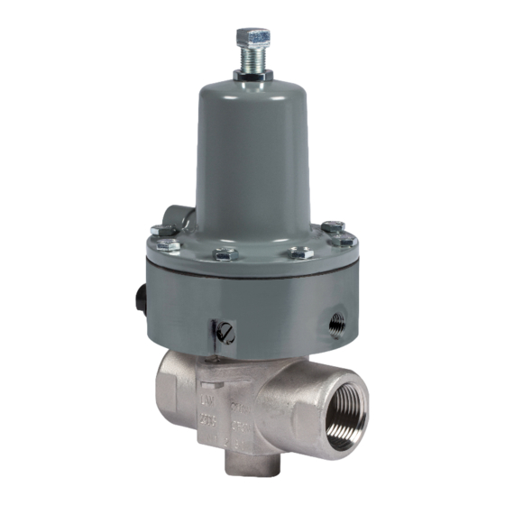
Type 119: Direct-operated valve used for on-
off or throttling control of noncorrosive or mildly
corrosive liquids and gases
Type 119EZ: Direct-operated valve with adjustable
opening speed for reliable startup operation on
gas burner systems
Type 119EZS: Type 119EZ equipped with solenoid
for valve to be operated by local control system
Body Sizes and End Connection Styles
Type 119:
BODY SIZE, NPT
3/4
1
1-1/4
Types 119EZ and 119EZS:
BODY SIZE, NPT
1
Maximum Inlet Pressure
10.3 bar / 150 psig
Spring Ranges
0.2 to 1.0 bar / 3 to 5 psig
0.3 to 1.4 bar / 5 to 20 psig
0.3 to 2.4 bar / 5 to 35 psig
2.1 to 4.1 bar / 30 to 60 psig
Maximum Control Pressure to Diaphragm
10.3 bar / 150 psig
1. The pressure/temperature limits in this Installation Guide, ASCO solenoid documentation and any applicable standard or code limitation should not be exceeded.
2. Pressure and/or the body end connection may decrease these maximum temperatures.
3. Not for use with hot water or Ammonia (NH
4. Minimum temperature for cast iron body is -29°C / -20°F.
CATEGORIES
FLUID TYPE
SEP
1
BODY MATERIAL
Cast Iron, WCC Steel
Cast Iron
BODY MATERIAL
Cast Iron, CF8M Stainless Steel
(1)
).
3
Maximum Pressure Drop
10.3 bar / 150 psig for all port diameters
7.9 bar / 115 psig for Type 119EZS with
ASCO™ 8320 Series solenoid
Proof Test Pressure
All Pressure Retaining Components have been
proof tested per Directive
Material Temperature Capabilities
Type 119:
MATERIAL
Nitrile (NBR)
Fluorocarbon (FKM)
(3)
Types 119EZ and 119EZS:
MATERIAL
Nitrile (NBR)
(4)
Fluorocarbon (FKM)
(3)
Type 119EZS Solenoid Temperature Capabilities
ASCO 8320 Series Solenoid:
0 to 52°C / 32 to 125°F
ASCO 8314 Series Solenoid:
-25 to 55°C / -13 to 131°F
Installation
!
Only qualified personnel should install
or service a valve. Valves should be
installed, operated and maintained
in accordance with international and
applicable codes and regulations, and
Emerson Process Management Regulator
Technologies Inc. instructions.
If the valve vents fluid or a leak develops
in the system, it indicates that service
is required. Failure to take the valve out
of service immediately may create a
hazardous condition.
Personal injury, equipment damage
or leakage due to escaping fluid or
bursting of pressure-containing parts
may result if this valve is overpressured
or is installed where service conditions
could exceed the limits given in the
Specifications section, or where
conditions exceed any ratings of the
adjacent piping or piping connections.
119 Series
(1)
(1)(2)
TEMPERATURE RANGE
-29 to 82°C / -20 to 180°F
-18 to 121°C / 0 to 250°F
TEMPERATURE RANGE
-40 to 82°C / -40 to 180°F
-18 to 121°C / 0 to 250°F
WARNING
(1)
Advertisement

Related Manuals for Emerson FISHER 119 Series


Summary of Contents for Emerson FISHER 119 Series
- Page 1 Type 119: applicable codes and regulations, and BODY SIZE, NPT BODY MATERIAL Emerson Process Management Regulator Technologies Inc. instructions. Cast Iron, WCC Steel If the valve vents fluid or a leak develops 1-1/4 Cast Iron...
- Page 2 119 Series Startup To avoid such injury or damage, provide pressurerelieving or pressure-limiting The valve is factory set at approximately the midpoint devices (as required by the appropriate of the spring range or the pressure requested, so code, regulation or standard) to an initial adjustment may be required to give the prevent service conditions from desired results.
- Page 3 119 Series 37A8078-D APPLY LUBRICANT L1 = Anti-seize compound lubricant L2 = Silicone grease lubricant 1. Lubricants must be selected such that they meet the temperature requirements. Figure 1. Type 119 Fuel Gas Valve Assembly TYPE 119EZ ERAA14665 APPLY LUBRICANT 1.
- Page 4 Technologies, Inc. All rights reserved. 01/19. McKinney, Texas 75070 USA Singapore 128461, Singapore The Emerson logo is a trademark and service mark of Emerson Electric T +1 800 558 5853 T +65 6777 8211 Co. All other marks are the property of their prospective owners.