TA DHR Series Getting Started Manual
Electrically heated plate
Hide thumbs
Also See for DHR Series:
- Getting started manual (16 pages) ,
- Getting started manual (33 pages) ,
- Getting started manual (58 pages)

Related Manuals for TA DHR Series


Summary of Contents for TA DHR Series
- Page 1 DHR Series and AR Series Electrically Heated Plate Getting Started Guide Revision E Issued November 2013...
- Page 2 TA Instruments may have patents, patent applications, trademarks, copyrights, or other intellectual prop- erty covering subject matter in this document. Except as expressly provided in written license agreement from TA Instruments, the furnishing of this document does not give you any license to these patents, trade- marks, copyrights, or other intellectual property.
-
Page 3: Introduction
Introduction Important: TA Instruments Manual Supplement Please click the TA Manual Supplement link to access the following important information supplemental to this Getting Started Guide: • TA Instruments Trademarks • TA Instruments Patents • Other Trademarks • TA Instruments End-User License Agreement •... -
Page 4: Notes, Cautions, And Warnings
Notes, Cautions, and Warnings This manual uses NOTES, CAUTIONS, and WARNINGS to emphasize important and critical instructions. In the body of the manual these may be found in the shaded box on the outside of the page. NOTE: A NOTE highlights important information about equipment or procedures. CAUTION: A CAUTION emphasizes a procedure that may damage equipment or cause loss of data if not followed correctly. -
Page 5: Electromagnetic Compatibility Standards
Electromagnetic Compatibility Standards For Australia and New Zealand AS/NZS CISPR11:2004 Limits and methods of measurement of electronic disturbance characteristics of industrial, scientific and medical (ISM) radio frequency equipment. For Canada ICES-001 Issue 4 June 2006 Interference-Causing Equipment Standard: Industrial, Scientific, and Medical Radio Frequency Generators. -
Page 6: Safety
Safety Do not attempt to service this instrument, as it contains no user-serviceable components. Required Equipment While operating this accessory, you must wear eye protection that either meets or exceeds ANSI Z87.1 standards. Additionally, wear protective clothing that has been approved for protection against the materials under test and the test temperatures. -
Page 7: Table Of Contents
Important: TA Instruments Manual Supplement ........ -
Page 8: Chapter 1: Introducing The Electrically Heated Plates
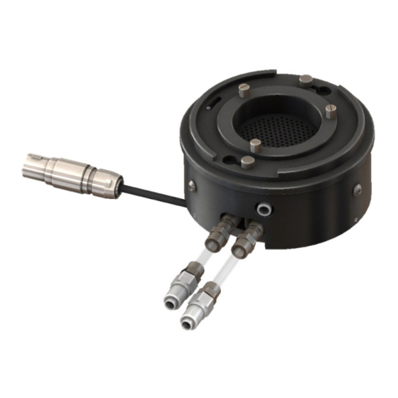
Chapter 1: Introducing the Electrically Heated Plates About the Electrically Heated Plates The Electrically Heated Plates (EHP) consist of a high temperature parallel plate and a cone and plate Smart Swap™ temperature system. It designed for use with the Discovery Series and AR-G2, AR2000ex, and AR 1500ex rheometers. -
Page 9: Electrically Heated Plates Components
Electrically Heated Plates Components The EHP consists of three main components (see the figure below). • An upper fixture that attaches to the rheometer head. This fixture contains electrical heating elements, cooling ducts, and purge duct. • A lower fixture that mounts on the rheometer Smart Swap connector. This fixture contains electrical heating elements and a cooling duct. - Page 10 WARNING: Do not use any tubing other than that provided by TA Instruments to connect the bracket to the upper and lower fixtures. If replacement tubing is required, please contact your local TA Instruments' representative or service engi- neer. AVERTISSEMENT: N'utilisez pas une tuyauterie autre que celle fournie par TA Instruments pour raccorder le support aux fixations supérieure et inférieure.
-
Page 11: System Specifications
System Specifications Refer to the table below for EHP system specifications: Table 1: Electrically Heated Plate System Specifications Temperature range Ambient to 400°C Maximum heating rate 30°C/min (uncontrolled) 10°C/min (controlled) ramp rate* Crash cooling flow rate No limits. Purge gas flow rates 5 L/min recommended (Set the lowest flow below 5 L/min that stops oxidation. -
Page 12: Chapter 2: Installing The Electrically Heated Plates
Chapter 2: Installing the Electrically Heated Plates The steps needed to attach the EHP to the rheometer involve the following: • Mounting and connecting the manifold. • Mounting and connecting the upper and lower fixture. • Attaching the geometry holder. •... -
Page 13: Installing The Ehp
Installing the EHP Follow the instructions below. Mounting and Connecting the Manifold Follow these instructions to install the EHP manifold: Ensure that the main air supply is turned off and depressurized. Mount the manifold to the rear of the rheometer using the four crosshead screws provided. For a DHR instrument, mount the adapter bracket onto the rear of the rheometer and then mount the manifold to the adapter. - Page 14 Connect one branch of the ‘Y’ piece to the filter regulator system using the 8-mm outer diameter white/ natural tubing provided. Insert the 8-mm to 6-mm reducer into the second branch of the ‘Y’ piece. Then connect this to the 6-mm ‘Y’...
-
Page 15: Mounting And Connecting The Upper And Lower Fixtures
Mounting and Connecting the Upper and Lower Fixtures Follow the instructions below to install the upper and lower fixtures on the rheometer. Refer to the figure below, which shows the upper and lower fixtures mounted, for reference. Figure 5 The EHP with cover up on left, and cover down on right (AR Series shown). Ensure that the rheometer is turned on. - Page 16 A schematic of the cooling air and gas purge outlet connections from the manifold is shown in the figure below. Gas purge Motor cooling Crash cool upper Crash cool lower Figure 7 Schematic of cooling air and gas purge outlets from upper and lower fixtures. Remove the plugs from the connectors on the cooling ducts.
-
Page 17: Attaching And Removing The Geometry Holder
Connect the crash cool upper exhaust pipe and lower exhaust pipe to the crash cool upper and lower outlets, respectively, using the compression fittings provided. Ensure that the pipes are pointing away from the flexible tubing. Figure 9 Crash cool upper exhaust pipe. Attaching and Removing the Geometry Holder The geometry holder and geometry holder spanner are shown in the figure below. -
Page 18: Removing The Geometry Holder
Removing the Geometry Holder Follow the instructions below to remove the geometry holder: Ensure that the rheometer is turned on. Raise the head to the maximum (use the Head UP button located on the instrument control panel). Grasp the geometry holder on the machined flats at the base, and unscrew from the instrument shaft by rotating the drawrod. - Page 19 Slide the cover over the upper fixture, engaging the bayonet fittings on the cover with the lugs on the upper fixture. Twist the cover to hold in place and remove the fixing tool. The cover is now in the up position, as shown in the figure below.
-
Page 20: Removing The Purge Gas Cover
Removing the Purge Gas Cover Follow these instructions to remove the purge gas cover: Raise the instrument head (use the Head UP button located on the instrument control panel). Lower the cover using the fitting tool, and bring it clear of the instrument upper and lower fixtures. About the View Cover An optional extra for the EHP is the view cover, shown below. -
Page 21: Setting The Gas Flow Rates
Setting the Gas Flow Rates The EHP cooling and purge gas flow rates are operated manually. The regulators and flow meters are mounted on the sides of the manifold. The gas purge regulator and flow meter are on the left of the mani- fold, the motor cooling regulator, and flow meter;... -
Page 22: Ehp Temperature Calibration Factors
EHP Temperature Calibration Factors Platinum Resistance Thermometers (PRT’s) are located in the lower pedestal, upper jacket assembly, and Upper Temperature Sensor (UTS) (this applies to the Discovery Series and AR-G2 with standard plates only). Depending on your configuration, it may be necessary to enter calibration factors into TRIOS Soft- ware. -
Page 23: Index
Index cautions 4 components 9 geometry holder 17 installing 13 installing upper and lower fixtures 15 introduction 8 specifications 11 temperature calibration factors 22 electromagnetic compatibility standards 4 gas flow rates setting 21 geometry holder 17 attaching 17 removing 18 instrument symbols 6 license agreement 3 manifold... - Page 24 Regulatory Compliance 4 regulatory compliance 4 safety 6 instrument symbols 6 Safety Standards 4 safety standards 4 TA Instruments offices 3 temperature calibration factor 22 trademarks 3 view cover 20 warnings 4 DHR/AR Series Electrically Heated Plate Getting Started Guide...
Need help?
Do you have a question about the DHR Series and is the answer not in the manual?
Questions and answers