
Related Manuals for TA PMG1


Summary of Contents for TA PMG1
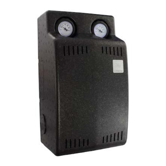
- Page 1 PMG1 PUMP/MIXER ASSEMBLY Installation Commissioning Operation Manual version 1.00 English...
-
Page 3: Table Of Contents
Table of contents Manual version 1.00 Safety requirements ............4 Disposal . -
Page 4: Safety Requirements
If you are connecting the PMG1 to an electrical system via a residual current device (RCD), use an RCD of type A which will detect pulsating direct currents and bears the following marking: Checking using a high voltage insulation tester may cause damage to the pump and the control elec- tronics. -
Page 5: Function Description
Function description Flow sensor The pump/mixer assembly PMG1 is used to control the tem- perature of the supplied heating water. The integral controller PMR1 is not used to independently control the PMG. Instead, it needs to be connected to a freely programmable controller (via CORA-DL or CORA wireless) and incorporated into the controller programming. - Page 6 Unscrew mounting plate of controller. Remove inner thermal insulation section. Install PMG1 on the wall; fit pipes. Insert flow sensor in the sensor well (above the pump) and secure it carefully (M2 Allen key). Refit inner thermal insulation section. Re-attach mounting plate of controller. The plate with the controller goes behind/below the plate in the pump assembly.
- Page 7 • For wired operation (CORA-DL): Undo 4 screws on the controller, install the CORA-DL wir- ing (see page 14) and re-fit the controller cover. Finally, plug in the mains cable. In every case, the PMG1 must be incorporated into the programming of the connected x2 controller (see page 16).
-
Page 8: Components
Components Flow tem- perature Return temperature Pump Controller Mixer motor Mixer valve... -
Page 9: Mixer Motor, Mixer Manual Mode
Mixer motor, mixer manual mode The mixer motor can be removed by pressing the retaining clip located underneath to the left. Once unlocked, the mixer motor can be removed by pulling it upwards. Retaining clip to right = closed Retaining clip to left = open Mixer motor locked in place and Mixer motor can be removed ready to operate... -
Page 10: Rotate Thermometers
Rotate thermometers The PMG1 can be installed in any direction and the thermometers (for flow and return temperature) can be rotated to improve readability. The retainer for the thermometers has 2 holes on the rear side. Simply press firmly through both holes to remove the thermometer, then reinsert it with the required rotation. -
Page 11: Pump Mode
Pump mode The installed pump has various control modes. Press the button next to the LEDs to switch to the next mode. The correct mode for standard applications is already set at the factory. The pump indicates its status (including control mode) with different combinations of the 5 LEDs. LEDs are either illuminated steadily, flash once every second, flash 12 times per second or are not illuminated. -
Page 12: Dimensions
Dimensions Dimensions of enclosure (thermal insulation cover) W x H x D = 250 x 450 x 200 mm... -
Page 13: Installation
Installation • Any installation direction (vertical or other). • Remove insulation cover, select fixing points, insert rawl plugs, secure module to wall. • Install and connect pipe connections (1" external thread connection). • Check all PMG connections for leaks and ensure that they are securely fitted. •... -
Page 14: Electrical Connection
Electrical connection The integral controller is ready wired at the factory. Only the connection to the x2 controller via may be required. Pump Mixer Mains 230 AC P N PE PE P N P1 P2 N OPE CL HLSC (NC) (optional) (S2, optional) The integral controller is connected with an x2 controller via CORA-DL (cable) or where applicable... -
Page 15: Operation Of The Controller And Led Indicators
Operation of the controller and LED indicators The controller is accessible after removing the thermal insulation cover. There are few setting options on the integral con- troller. Parameters such as set temperature are specified in the programming of the x2 controller. Reset button LEDs Manual/automat-... -
Page 16: Data Transfer With Cora
Data transfer with CORA Connection with an x2 controller is possible via CORA-DL or where applicable via CORA wireless. Both simultaneously is not possible. Programming The pump assembly is incorporated into the pro- gramming of the x2 controller used. We recommend using the TAPPS2 programming software. -
Page 17: Output Variables
Blocking protection Pump (Yes/No) Activation of blocking protection for pump/mixer Mixer (Yes/No) Interval time If the pump/mixer (depending on above setting) has not moved for this period of time, the respective component is activated briefly (and the meter reset) to prevent corrosion. Speed / PWM Input variable Process variable of input signal for pump speed ("Pump"... -
Page 18: Programming Example
Programming example Example of typical PMG actuation via a heating circuit control function. -
Page 19: Wireless System
(= 2 clicks within 2 seconds). Pairing is then enabled for 5 minutes. For pairing, you will need to enter the CORA ID of the PMG1 on the control device. This can be found on a label on the front of the integral controller. -
Page 20: Technical Data
Technical data Max. operating pressure 8 bar Max. operating temperature Continuously 95 °C, briefly up to 120 °C Connection thread 1" external thread DL bus load Maximum electrical rating, (pump + controller + mixer) 90 W Pump Grundfos UPM3 K Hybrid 25-70 Mixer motor NVM08 KVS 5.5 Mixer runtime... - Page 21 Technische Alternative RT GmbH Address: A-3872 Amaliendorf, Langestraße 124 This declaration of conformity is issued under the sole responsibility of the manufacturer. Product name: PMG1 Product brand: Technische Alternative RT GmbH Product description: Pump/mixer assembly The object of the declaration described above is in conformity with Directives:...
- Page 24 Processing is accelerated if an RMA number is applied for via our home page www.ta.co.at. A prior clarification of the defect with our technical support is necessary. 6. Services provided under warranty result neither in an extension of the warranty period nor in a resetting of the warranty period.
Need help?
Do you have a question about the PMG1 and is the answer not in the manual?
Questions and answers