
Related Manuals for TA DISCOVERY DMA 850


Summary of Contents for TA DISCOVERY DMA 850
- Page 1 DiScovery DMA 850 DynAmIc mechAnIcAl AnAlyzeR Getting Started Guide Revision F Issued April 2021...
- Page 2 TA Instruments may have patents, patent applications, trademarks, copyrights, or other intellectual prop- erty covering subject matter in this document. Except as expressly provided in written license agreement from TA Instruments, the furnishing of this document does not give you any license to these patents, trademarks, copyrights, or other intellectual property.
-
Page 3: Introduction
Introduction Important: TA Instruments Manual Supplement Please click the TA Manual Supplement link to access the following important information supplemental to this Getting Started Guide: • TA Instruments Trademarks • TA Instruments Patents • Other Trademarks • TA Instruments End-User License Agreement •... -
Page 4: Notes, Cautions, And Warnings
Notes, Cautions, and Warnings This manual uses NOTES, CAUTIONS, and WARNINGS to emphasize important and critical instructions. In the body of the manual these may be found in the shaded box on the outside of the page. NOTE: A NOTE highlights important information about equipment or procedures. CAUTION: A CAUTION emphasizes a procedure that may damage equipment or cause loss of data if not followed correctly. -
Page 5: Electromagnetic Compatibility Standards
à la réception radio dans de tels environnements. Supplier’s Declaration of Conformity 47 CFR § 2.1077 Compliance Information Unique Identifier: 986000.901 Responsible Party: TA Instruments 159 Lukens Drive New Castle, DE 19720 302-427-4000 www.tainstruments.com FCC Compliance Statement: This device complies with Part 15 of the FCC rules. -
Page 6: Safety
If you are not trained in electrical procedures, do not remove the cabinet covers unless specifically instructed to do so in the manual. Maintenance and repair of internal parts must be performed only by TA Instruments or other qualified service personnel. -
Page 7: Electrical Safety
Vac are present in this system.. WARNING: High voltages are present in this instrument. Maintenance and repair of internal parts must be performed only by TA Instruments or other qualified service personnel. AVERTISSEMENT: Présence de tensions élevées dans cet instrument. La maintenance et la réparation des pièces internes doivent être effectuées uniquement par TA Instruments ou tout... - Page 8 WARNING: Potential Asphyxiant Liquid nitrogen can cause rapid suffocation without warning. Store and use in an area with adequate ventilation. Do not vent the Gas Cooling Accessory (GCA) in confined spaces. Do not enter confined spaces where nitrogen gas may be present unless the area is well ventilated.
-
Page 9: Thermal Safety
1000 kPa gauge (150 psig). • If you are installing the DMA with the ACA, the tubing supplied by TA Instruments with the accessory must be used to connect it to the air filter regulator. The ACA has a pressure relief valve limiting the pressure supplied by the ACA to 500 kPa gauge (70 psig) maximum. -
Page 10: Dma Submersion Clamps Warning
à air ne doit pas dépasser une pression manométrique de 1000 kPa (150 psig). • Si vous installez le DMA avec l'ACA, la tuyauterie fournie par TA Instruments avec l'accessoire doit être utilisée pour le raccordement au régulateur du filtre à air. L'ACA est équipé d'une sou- pape de détente de pression qui limite la pression manométrique fournie par l'ACA à... -
Page 11: Lifting The Instrument
Lifting the Instrument The DMA is a heavy instrument. In order to avoid injury, particularly to the back, please follow this advice: WARNING: Close the furnace before moving the instrument, even for a short distance. Use two people to lift and/or carry the instrument. The instrument is too heavy for one person to handle safely. -
Page 12: Table Of Contents
Table of Contents Introduction ..............................2 Important: TA Instruments Manual Supplement ................... 2 Notes, Cautions, and Warnings ......................3 Regulatory Compliance .......................... 3 Safety Standards ..........................3 Electromagnetic Compatibility Standards ....................4 Supplier’s Declaration of Conformity ....................4 Safety ..............................5 Instrument Symbols......................... - Page 13 Air Bearing Gas and Air Filter Regulator Connections ............... 32 Connecting the Air Filter Regulator (Lab air source only) ............33 Connecting the Air Filter Regulator to the Air Compressor Accessory (ACA)......34 Connecting the Cooling Gas Line ....................37 Cooling Gas Connections ......................
-
Page 14: Chapter 1: Introducing The Dma 850
The DMA instrument works in conjunction with a controller, TA Instruments TRIOS software, and an environmental system to make up a thermal analysis system. The environmental system may be one or more of a controlled temperature chamber (oven) or Relative Humidity chamber. -
Page 15: Dma System Components
It has control features such as the ability to set a tempera- ture, move the shaft to help install a sample, control the motor mode, and start or stop an experiment. The DMA developed by TA Instruments offers the following features: •... -
Page 16: Air Filter Regulator Assembly
The air source supplying the air filter regulator can come from a central laboratory supply or from the TA Instruments Air Compressor Accessory (ACA). Inlet pressure should be 80–150 psi from the central labo- ratory supply, and outlet pressure set for 60 psi. -
Page 17: The Dma 850 User Interface
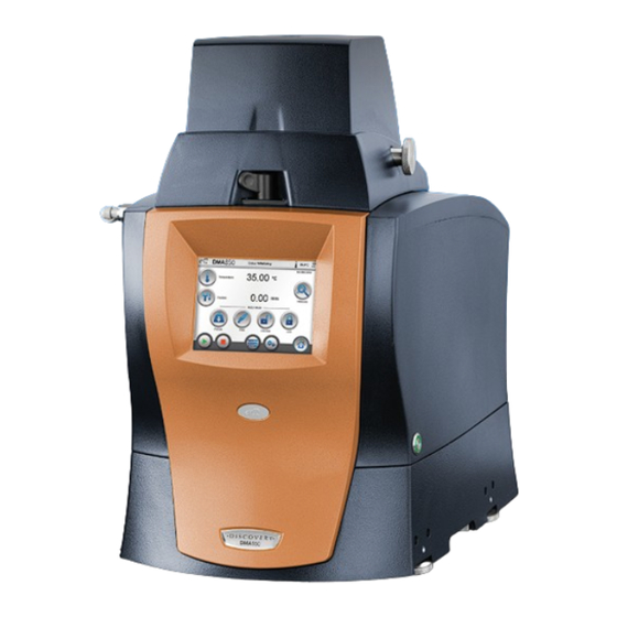
The DMA 850 User Interface The DMA 850 instrument has a built-in integrated display and keypad in the form of a user interface for local operator control. The functions on the screen change depending upon the menu you are using. This section briefly describes the basic layout of these functions. -
Page 18: View Panel
Table 1: Primary Function Buttons on the User Interface Button Name Description Signals Displays real-time signal data generated directly from the instrument. Signals can be selected and reordered within the real-time signal section of the TRIOS Control panel. System Allows the selection of cooling accessories, and access to user interface calibration, network settings, system messages, and service information. - Page 19 Table 2: View Panel Functions on the User Interface Button Name Description Motor Mode: Preload Allows the application of the preload force prior to the start of the test. The applied force value is read from the test currently programmed in TRIOS.
-
Page 20: System View Panel
System View Panel The System View Panel displays the Network connection information for the DMA and the TRIOS host computer connected to the DMA 850. Additional system settings accessible from this screen are listed below.. Table 3: System View Panel Functions on the User Interface Button Name Description Touch Calibration... -
Page 21: Signal View Panel
Table 3: System View Panel Functions on the User Interface Button Name Description Cooling Accessories The Cooling Accessories button displays a list of available cooling accessories. Once the accessory is installed, use this screen to activate the accessory. Position Calibration Use the Position Calibration function to calibrate the DMA 850 posi- tion when it is moved or turned off, or the position calibration was unsuccessful during Initialization. -
Page 22: Instrument Specifications
Instrument Specifications The tables found on the following pages contain the technical specifications for the DMA. Table 4: DMA Technical Specifications Item/Area Specifications Dimensions Depth: 47 cm (18.5 in) Width: 38 cm (15 in) Height: Standard Furnace open: 68.5 cm (27 in) Standard Furnace closed: 53.5 cm (21 in) Weight with Standard Furnace 34 kg (75 lbs) - Page 23 Table 5: Temperature Control Specifications Item/Area Specifications Isothermal Stability ± 0.1°C above 50°C; ± 1.0°C below 50°C a. The use of nitrogen as the air bearing gas is highly recommended when temperatures exceed 400°C. Table 6: Experimental Specifications Item/Area Specifications Modulus Range 1 kPa to 1000 GPa Modulus Precision...
-
Page 24: Options And Accessories
Options and Accessories Several optional clamps and accessories are available from TA Instruments to be used with the DMA 850. A brief description of each one follows. For more information refer to the Help documentation. Clamps The DMA 850 utilizes several different types of clamps. These clamps can be classified as either tension- ing or non-tensioning clamps. -
Page 25: Gas Cooling Accessory (Gca)
The ACS is a unique multi-stage air chiller system for subambient temperature control and general cooling of select instrumentation from TA, including the DMA 850. The ACS units feature durable compressors, small footprint, uninterrupted operation, are CFC-free, and for specified temperature ranges, eliminate the recurring cost and safety concerns associated with handling and use of liquid nitrogen. -
Page 26: Nitrogen Purge Cooler Accessory (Npc)
Nitrogen Purge Cooler Accessory (NPC) The Nitrogen Purge Cooler (P/N 986310.901), is an optional accessory for extending the temperature range of the DMA 850 standard furnace to –160°C. The NPC consists of a 2.5 L Dewar flask that contains a copper coil tube. The furnace is cooled by purging nitrogen gas through the copper coil immersed in the liquid nitrogen-filled Dewar flask. -
Page 27: Air Compressor Accessory (Aca)
Air Compressor Accessory (ACA) The Air Compressor Accessory P/N 986350.901) is a compact unit that connects directly to the air filter regulator. It supplies compressed air to the air filter regulator for the DMA air bearing gas supply when a compressed air source is not available. -
Page 28: Chapter 2: Installing The Dma
• Connecting cables and gas lines. It is recommended that you have your DMA installed by a TA Instruments Service Representative; call for an installation appointment when you receive your instrument. CAUTION: To avoid mistakes, read this entire chapter before you begin installation. -
Page 29: Inspecting The System
When you receive your DMA 850, look over the instrument and shipping container carefully for signs of shipping damage, and check the parts received against the enclosed shipping list. • If the instrument is damaged, notify the carrier and TA Instruments immediately. • If the instrument is intact but parts are missing, contact TA Instruments. -
Page 30: Connecting Cables And Lines
CAUTION: Drying out the instrument may be needed, if it has been exposed to humid conditions. Certain ceramic materials used in this equipment may absorb moisture, causing leakage currents to exceed those specified in the applicable standards until moisture is eliminated. It is important to be certain that the instrument ground is adequately connected to the facilities ground for safe opera- tion. -
Page 31: Ports
Inlet for cooling the furnace through air cooling and the NPC (830 kPa gauge [120 psig] maximum pressure) EXT INPUT TA Instruments Internal Use only. EVENT Capable of the following functions: general purpose relay contact clo- sure, or general purpose input 4 – 24 VDC for external syncing. This port is used for ACS operation. - Page 32 EXT INPUT EVENT CAN BUS MAIN POWER COM1 ETHERNET Figure 11 Back panel. COOLING GAS OUTLET AIR BEARING GAS INLET Figure 12 Ports on the right rear of the instrument. Discovery DMA Getting Started Guide Page 31...
-
Page 33: Air Bearing Gas And Air Filter Regulator Connections
DMA 850’s air bearings. (See the Help for information on maintaining the air filter regulator.) An effi- cient system ensures minimum pressure loss and removal of contaminants such as water, oil, dirt, rust, and other foreign materials. TA Instruments recommends the following minimum criteria for the air being sup- plied to the Air Filter Regulator: •... -
Page 34: Connecting The Air Filter Regulator (Lab Air Source Only)
• Water vapor dew point at 690 kPa gauge (100 psig) = 0°C (32°F) NOTE: If you are using a desiccant dryer, it is best to install it after the Air Filter Regulator. Connecting the Air Filter Regulator (Lab air source only) To connect the air filter regulator to the instrument, refer to Figure 13 above and follow the instructions... -
Page 35: Connecting The Air Filter Regulator To The Air Compressor Accessory (Aca)
à air. Cela permet de condenser toute la moisissure contenue dans l'air et d'améliorer l'efficacité du régulateur du filtre à air. CAUTION: Do not attempt to open the ACA; there are no customer-serviceable parts. Contact TA Instruments for service. - Page 36 Push one end of the thin 1/8-inch tubing into the air filter regulator fitting. Insert the tubing into the fitting until it cannot go in any further. The full ten feet of tubing supplied with the ACA must be used to connect the ACA to the air filter regulator.
- Page 37 Installing the Step-Down Transformer for the ACA (240 V regions only) Every ACA unit is shipped with a step-down transformer and converter. To install the transformer: Plug the ACA power cable into the front of the transformer. Figure 17 ACA connected to the step-down transformer. Attach the converter to the plug on the back of the transformer.
-
Page 38: Connecting The Cooling Gas Line
Connecting the Cooling Gas Line The cooling gas connection supplies the DMA furnace with gas to cool the furnace to room temperature and heat the submersion clamp fluid only when the Gas Cooling Accessory (GCA) or Air Cooling System (ACS) is not connected to the DMA. (See the GCA Getting Started Guide, ACS Getting Started Guide, or the Help for further information on the GCA or ACS.) Follow the procedure below to install the cooling gas line for air cool: Locate the Cooling Gas fitting, a 1/4-inch Legris fitting on the left side of the DMA cabinet back, marked... -
Page 39: Setting Up System Communication
Locate the 1/4-inch Cooling Gas outlet fitting on the rear of the instrument. Insert the 1/4-inch tubing into the Cooling Gas outlet fitting. COOLING GAS OUTLET Figure 21 Cooling gas outlet tubing. Setting Up System Communication The instrument and controller must connect to a router, switch, or LAN. Refer to TRIOS Software Installation Instructions for more details. -
Page 40: Connecting The Power Cables
Connecting the Power Cables NOTE: A <HAR>-marked (harmonized) power cable meeting the standards of the country of installation is required for the European Economic Area. Refer to Figure 22 above for power ports on the back of the Power Control Box. Make sure the DMA Power Control Box switch is in the Off (0) position. -
Page 41: Starting The Dma
Starting the DMA Check all connections between the DMA 850, the Power Control Box, and the controller. Make sure each component is plugged into the correct connector. Verify that the pressure into the Air Bearings is set for 60 psi. Set the power switch on the Power Control Box to the ON (I) position. -
Page 42: Shutting Down The Dma
Shutting Down the DMA Before you decide to power down your instrument, consider the following: • All of the components of the DMA 850 system are designed to be powered on for long periods. • The electronics of the DMA 850 and the controller perform more reliably if power fluctuations caused by turning units on and off are minimized. -
Page 43: Installing And Removing The Standard Furnace
Installing and Removing the Standard Furnace Installing the Furnace Remove the 4 screws from the instrument cover plate and set aside the screws and plate for reinstallation later on in the procedure Figure 25 Removing the instrument cover plate. Insert the furnace mechanism housing into the opening. Figure 26 Insert furnace mechanism housing. -
Page 44: Installing The Moisture Guard Accessory
Secure the furnace mechanism housing with 4 screws. Figure 27 Install the filler plate supplied with the furnace accessory. Figure 28 Install filler plate. NOTE: If the DMA 850 furnace will be used with ACS or GCA accessories, proceed to “Installing the Moisture Guard Accessory”... - Page 45 The moisture guard (P/N 986327.001) is used with the ACS or GCA accessories to keep condensation from dripping into the electronics on the back of the DMA 850. NOTE: If the furnace was previously installed, the furnace cable and ground wire will already be secured to the rear panel.
- Page 46 If the furnace cable and ground wire are secured to the instrument, remove the furnace cable clamp screw and the ground wire screw. If they are not attached, skip to step Furnace cable clamp screw Ground wire screw Figure 31 Furnace cable clamp and ground wire screws. Attach the moisture guard using the left, right, and center rear panel screws that were removed in step Furnace cable clamp screw...
-
Page 47: Removing The Furnace
Reinstall the ground wire screw to secure the ground wire to the rear panel. Moisture guard screw securing furnace cable clamp to moisture guard Ground wire screw reinstalled Figure 33 Furnace cable and ground wire secured. Raise the furnace and make sure the furnace cable has sufficient slack in the clamp once the furnace has reached the top of travel in the Furnace Guide. -
Page 48: Installing The Single/Dual Cantilever Clamp
Installing the Single/Dual Cantilever Clamp When you initially receive the DMA 850, a clamp will need to be installed. The procedures that follow explain the installation and removal of the single/dual cantilever clamp, which is the standard clamp used on the DMA. Later, if a different sample geometry is required, you can install the appropriate clamp for the experiment. - Page 49 Line up the fixed clamp with the mounting posts and tighten the four hex screws using the torque wrench with 9/64”bit. Fixed clamp Hex screws (2 shown) Mounting post Figure 37 Installing the fixed clamp. CAUTION: The fixed clamp should be installed with the torque wrench set to 10 in.lb. Over torquing the fixed clamp can twist the mounting posts and may damage the instrument.
-
Page 50: Removing The Single/Dual Cantilever Clamp
Removing the Single/Dual Cantilever Clamp The following procedure is used to remove the clamp. If a sample is installed, remove it before proceeding. Press the Lock button to lock the clamp in place. Loosen, but do not remove, the four hex screws holding the fixed clamp on the mounting posts. See Figure Lift the fixed clamp off the four supports.Take care not to damage the thermocouple. -
Page 51: Chapter 3: Use, Maintenance, & Diagnostics
Chapter 3: Use, Maintenance, & Diagnostics Using the DMA 850 All of your DMA 850 experiments will have the following general outline. In some cases, not all of these steps will be performed. The majority of these steps are performed using the instrument control software. The instructions needed to perform these actions can be found in the Help;... -
Page 52: Calibrating The Dma 850
Calibrating the DMA 850 To obtain accurate experimental results, you should calibrate the DMA 850 when you first install it. For the best results, you should recalibrate periodically. A brief description of each of the calibrations is outlined below. For details on how to perform each calibration, refer to the Help accessed through the instrument control software. -
Page 53: Running A Dma 850 Experiment
Running a DMA 850 Experiment All of your DMA 850 experiments will have the following general outline. In some cases, not all of these steps will be performed. See the instrument control software Help for anything not covered in this manual. Basic Experimental Steps Choose, install, and calibrate the clamp appropriate for the sample shape and modulus range. - Page 54 Loosen the screw(s) on the thermocouple mounting bracket(s). Move the thermocouple(s) up or down, as needed, or bend to the desired angle. Retighten the screw in the bracket(s). If needed, adjust the angle of the thermocouple tip so that it is close to, but not touching, the sample. You may need to bend the thermocouple in order to get it closer to the sample.
-
Page 55: Selecting The Operating Mode
Selecting the Operating Mode There are multiple operating modes available for the DMA 850. Each mode listed in the table below reflects a different class of experiment that can be performed. Before you can begin an experiment, you need to select an operating mode using the instrument control software. If you are upgrading to Discovery from Q Series™, use the Equivalent column of the table to help you determine the mode for DMA 850 that is equivalent to the mode used for Q800. -
Page 56: Performing Experiments
Table 9: Operating Mode Q800 Test Equivalent DMA 850 Test Oscillation Temperature Ramp (Multifrequency) Oscillation Temperature Sweep (Multifrequency) Oscillation Temperature Sweep (Multifrequency) Oscillation Time Sweep Oscillation Fatigue Tests DMA Creep Creep TTS Stress Control Creep TTS Force DMA Creep Creep Stress Control Creep Recovery Force... - Page 57 NOTE: Use the Measure Again After Method Equilibration option on the Advanced Parameters window to adjust for dimension changes in the sample after the sample temperature equilibrates at the lower tem- perature setting. This option is applicable to film/fiber tension, compression, and penetration clamps only. Load the desired sample.
-
Page 58: Starting An Experiment
The primary maintenance procedures described in this section are the customer’s responsibility. Any fur- ther maintenance should be performed by a representative of TA Instruments or other qualified service per- sonnel. Consult the Help documentation installed with the instrument control software for further information. -
Page 59: Cleaning The User Interface
Cleaning the User Interface You can clean the DMA 850 user interface as often as you like. The user interface should be cleaned with a household liquid glass cleaner and soft cloth. Wet the cloth, not the user interface, with the glass cleaner and then wipe off the screen and surrounding surfaces. -
Page 60: Replacement Parts
Replacement Parts Replacement parts for the DMA 850 that are available from TA Instruments are listed below. Refer to the tables below when ordering parts. Table 10: DMA 850 Accessory Kit (986018.901) Items (see Appendix A) Part Number Description 986018.901 DMA 850 Accessory Kit (includes all items below) 280037.000... - Page 61 Table 11: Additional Replacement Parts Part Number Description 251470.025 Ethernet cable (7.7m [25 foot], shielded) 573046.001 Power cord 120 V 985724.901 Control thermocouple (88.9 mm length) 985724.902 Sample thermocouple (127 mm length) 980228.902 Glass support cloth (0.205 mm thick, 32.92 m length) 984309.901 PET film samples 3.5 cm (1.5 inch) long (10) 984310.901...
- Page 62 Table 12: Clamp Kits Part Number Description 984048.901 8 mm single/dual cantilever clamp kit 984047.901 20 mm single/dual cantilever clamp kit 984015.901 35 mm single/dual cantilever clamp kit 984026.901 Three-point bending clamp kit (5, 10, and 15 mm lengths) 984014.901 Three-point bending clamp kit (20 and 50 mm lengths) 984018.901 Parallel plate compression clamp kit (includes 15 and 40 mm plates)
- Page 63 Table 13: DMA 850 Accessories Part Number Description 405000.902 ACS-3 Chiller System 220–230 VAC, 50 Hz 986300.901 DMA 850 Air Chiller Panel (for use with the ACS-2 and ACS-3 Air Chiller Systems) Discovery DMA Getting Started Guide Page 62...
-
Page 64: Appendix A: Dma 850 Accessory Case Contents
Appendix A: DMA 850 Accessory Case Contents Accessory Case Contents Top Layer The following items are stored in the top layer DMA 850 accessory case: Discovery DMA Getting Started Guide Page 63... -
Page 65: Bottom Layer
Bottom Layer The following items are stored in the bottom layer DMA 850 accessory case: Discovery DMA Getting Started Guide Page 64...
Need help?
Do you have a question about the DISCOVERY DMA 850 and is the answer not in the manual?
Questions and answers