TA DHR Series Getting Started Manual
Immobilization cell
Hide thumbs
Also See for DHR Series:
- Getting started manual (33 pages) ,
- Getting started manual (58 pages) ,
- Getting started manual (24 pages)

Related Manuals for TA DHR Series


Summary of Contents for TA DHR Series
- Page 1 DHR Series Immobilization Cell Getting Started Guide Revision D Issued November 2014...
- Page 2 TA Instruments may have patents, patent applications, trademarks, copyrights, or other intellectual prop- erty covering subject matter in this document. Except as expressly provided in written license agreement from TA Instruments, the furnishing of this document does not give you any license to these patents, trade- marks, copyrights, or other intellectual property.
-
Page 3: Introduction
Getting Started Guide: • TA Instruments Trademarks • TA Instruments Patents • Other Trademarks • TA Instruments End-User License Agreement • TA Instruments Offices DHR Series Immobilization Cell Getting Started Guide Page 3... -
Page 4: Notes, Cautions, And Warnings
EN 61010-2-010:2003 Particular requirements for laboratory equipment for the heating of materials + Amendments. For United States UL61010-1:2004 Electrical Equipment for Laboratory Use; Part 1: General Requirements. UL61010A-2-010:2002 Particular requirements for laboratory equipment for the heating of materials + Amendments. DHR Series Immobilization Cell Getting Started Guide Page 4... -
Page 5: Electromagnetic Compatibility Standards
Table 1 - Basic immunity test requirements. For the United States CFR Title 47 Telecommunication Chapter I Federal Communications Commission, Part 15 Radio frequency devices (FCC regulation pertaining to radio frequency emissions). DHR Series Immobilization Cell Getting Started Guide Page 5... -
Page 6: Safety
Please heed the warning labels and take the necessary precautions when dealing with these areas. This Getting Started Guide contains cautions and warnings that must be followed for your own safety. DHR Series Immobilization Cell Getting Started Guide Page 6... -
Page 7: Cautions And Warnings
MISE EN GARDE: La plaque Peltier peut être endommagée si l'instrument est utilisé sans écoulement d'eau dans la plaque Peltier. Il existe un dispositif de protection contre la surchauffe qui s'active si le dispositif devient trop chaud. DHR Series Immobilization Cell Getting Started Guide Page 7... -
Page 8: Table Of Contents
Overview ............................... 9 System Specifications ..........................11 Ramp Rate............................11 Chapter 2: Installing the Immobilization Cell ..................12 Removing the Immobilization Cell...................... 15 Chapter 3: Using the Immobilization Cell ....................16 DHR Series Immobilization Cell Getting Started Guide Page 8... -
Page 9: Chapter 1: Introducing The Immobilization Cell
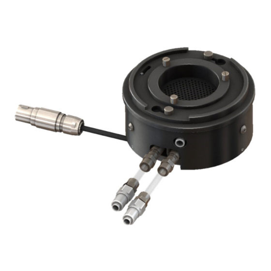
The temperature of the perforated platform is controlled by Peltier elements in the base of the unit. These heat or cool the specially shaped inner jacket, which transfers the temperature to the platform. Figure 2 DHR Series Immobilization Cell Getting Started Guide Page 9... - Page 10 NOTE: A vacuum pump is not supplied as part of the system. NOTE: You should consider installing a vapour trap to protect your vacuum pump and waste management manifold if the vapour extracted from your sample is likely to damage these components. DHR Series Immobilization Cell Getting Started Guide Page 10...
-
Page 11: System Specifications
Plot a graph of temperature vs. time (min) and take the derivative. Inspect the derivative curve over your temperature range of interest. The maximum sustainable rate will be the lowest value on the derivative curve. DHR Series Immobilization Cell Getting Started Guide Page 11... -
Page 12: Chapter 2: Installing The Immobilization Cell
Press the Release button on the control panel, as shown below. A continuous green light indicates that the attachment can be fitted. Control panel Figure 4 Control panel. NOTE: The release state will only stay active for 10 seconds. DHR Series Immobilization Cell Getting Started Guide Page 12... - Page 13 Figure 6 Connecting power cable and fluid hoses. When the green status light turns off, the Immobilization Cell is correctly installed. Attach the 50 mm Parallel Plate to the motor shaft. DHR Series Immobilization Cell Getting Started Guide Page 13...
- Page 14 11 Connect the 4-pin event cable from Event B on the rear of the rheometer to the Event connection. Signal port Power port AIR IN connection Supply/Return connections for Peltier Supply/Return connections for motor cooling Figure 8 Cable connections on rheometer back panel. DHR Series Immobilization Cell Getting Started Guide Page 14...
-
Page 15: Removing The Immobilization Cell
Release button location. Press the Release button again. A continuous green light indicates that you can remove the Immobilization Cell. Remove the Immobilization Cell from the rheometer. DHR Series Immobilization Cell Getting Started Guide Page 15... -
Page 16: Chapter 3: Using The Immobilization Cell
11 Raise the head and remove the platform, substrate, and retaining ring as once piece for easy cleaning. Retaining ring Perforated platform Cell body Figure 9 DHR Series Immobilization Cell Getting Started Guide Page 16...
Need help?
Do you have a question about the DHR Series and is the answer not in the manual?
Questions and answers