
Related Manuals for TA DTC-300


Summary of Contents for TA DTC-300
- Page 1 THERMAL CONDUCTIVITY METER DTC-300 getting Started guide Revision E Issued April 2020...
- Page 2 TA Instruments. Otherwise, TA Instruments does not guarantee any results and assumes no obligation or liability. TA Instruments also reserves the right to revise this document and to make changes without notice.
-
Page 3: Introduction
Introduction Important: TA Instruments Manual Supplement Please click the TA Manual Supplement link to access the following important information supplemental to this Getting Started Guide: • TA Instruments Trademarks • TA Instruments Patents • Other Trademarks • TA Instruments End-User License Agreement •... -
Page 4: Notes, Cautions, And Warnings
Please heed the warning labels and take the necessary precautions when dealing with those parts of the instrument. The DTC-300 Getting Started Guide contains cautions and warnings that must be followed for your own safety. -
Page 5: Electromagnetic Compatibility Standards
This device complies with Part 15 of the FCC rules. Operation is subject to the following two conditions: (1) This device may not cause harmful interference, and (2) this device must accept any interference received, including interference that may cause undesired operation. DTC-300 Getting Started Guide Page 4... -
Page 6: Safety
AVERTISSEMENT: Débranchez toujours l'instrument avant de procéder à la maintenance. WARNING: No user serviceable parts are contained in the DTC-300. Maintenance not specified in the DTC-300 Getting Started Guide and repairs must be performed by TA Instruments or other qualified service personnel only. -
Page 7: Electrical Safety
DANGER: Because of the high voltages in this instrument, maintenance and repair of internal parts must be performed by TA Instruments or other qualified service personnel only. DANGER: À cause de la présence de tensions élevées dans cet instrument, la maintenance et la réparation des pièces internes doivent être effectuées uniquement par TA Instruments ou tout... -
Page 8: Table Of Contents
DTC-300 Front Panel ....................... 12 DTC-300 Back Panel ......................14 Test Stack ..........................15 Instrument Specifications ......................16 Chapter 2: Installing the DTC-300 System ................18 Unpacking/Repacking ........................18 Installing the System ........................18 Inspecting the System ......................18 Choosing a Location ....................... 19 In ............................ - Page 9 Starting the DTC-300 System ....................23 Shutting Down the DTC-300 System ..................24 Running a DTC-300 Experiment ....................24 Sample Requirements ......................24 Low-Temperature Testing ....................... 25 Loading the Sample ......................25 Testing the Sample ......................26 High-Temperature Testing ...................... 27 Loading the Sample ......................
- Page 10 Uninstalling the Stack Spacer ....................51 Installing the Stack Spacer ...................... 52 Uninstalling and Installing the Bottom Stack ................53 Uninstalling the Bottom Stack ....................53 Installing the Bottom Stack ..................... 54 Replacement Parts ......................... 55 DTC-300 Getting Started Guide Page 10...
-
Page 11: Chapter 1: Introducing The Dtc-300
0.1 to 30 W/(m.K). These include some metals and ceramics, polymers, com- posites, glass, rubber, and carbon products. The DTC-300 can also be used to test thin samples like paper products and polymeric films. Non-solids of high viscosity can be tested using a special container to hold the material. -
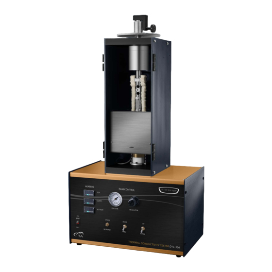
Page 12: Dtc-300 System Components
The movement of the test stack is controlled with the UP/DOWN, FREE/MOVE, and SPEED switches. Refer to Figure 2 below for the locations of knobs, switches, and indicators on the DTC-300 front panel and refer to Table 1 for a description of their functions. - Page 13 Moves the top stack up/down Air pressure gauge Air pressure gauge for monitoring air pressure applied to the top stack Air pressure regulator knob Air pressure regulator allows you to adjust the air pressure to the top stack DTC-300 Getting Started Guide Page 13...
-
Page 14: Dtc-300 Back Panel
DTC-300 Back Panel The DTC-300 back panel has five ports. Figure 3 below shows the rear connections and Table 2 provides a description of the function of each port. RS232 MAIN POWER switch MAIN POWER port AIR IN DRAIN Figure 3 DTC-300 rear panel connections. -
Page 15: Test Stack
Figure 4 Test stack on the DTC-300. DTC-300 Getting Started Guide Page 15... -
Page 16: Instrument Specifications
USA NEMA 6-15P style plug; the 110V instrument power cord comes supplied with a USA NEMA 5–15P style plug. The TA Representative installing the instrument will pro- vide the appropriate power cable for the geographical location where the instrument is being installed. - Page 17 Test Method ASTM E1530 Thermal Conductivity Range 0.1 – 40W/mK Thermal Resistance Range Low-Range: 0.0005 – 0.010 m Mid-Range: 0.002 – 0.020 m K/W Hi-Range: 0.01 – 0.05 m Accuracy ± 3% Reproducibility ± 2% DTC-300 Getting Started Guide Page 17...
-
Page 18: Chapter 2: Installing The Dtc-300 System
You may wish to retain all of the shipping hardware, the plywood, and boxes from the instrument in the event you wish to repack and ship your instrument. Installing the System Before shipment, the DTC-300 is inspected both electrically and mechanically so that it is ready for opera- tion upon proper installation. Installation involves the following procedures: •... -
Page 19: Choosing A Location
Choosing a Location Because of the sensitivity of DTC-300 experiments, it is important to choose a location for the instrument using the following guidelines. The DTC-300 system should be: • A temperature and humidity controlled area. • A clean, vibration-free environment. -
Page 20: Moving The Instrument
Connecting the Utilities Connecting the Power Plug the power cord from the MAIN POWER port on the back of the DTC-300 to an electrical outlet rated in accordance with the power input information on the back of the instrument. WARNING: Only use a mains power cable that meets the ratings displayed on the back of the instrument being installed/reinstalled. -
Page 21: Connecting The Air Supply
If a hose barb and clamp are supplied, affix the hose barb to an appropriately sized and pressure rated tube, and then insert the hose barb into the connector on the rear of the DTC-300 in the same fashion as described above. -
Page 22: Connecting The Coolant
CAUTION: Never operate the DTC-300 without coolant flowing through the heat sink. MISE EN GARDE: N'utilisez jamais le DTC-300 en l'absence du fluide caloporteur dans le dissipa- teur de chaleur. Insert the plastic fittings attached to the coolant hoses (supplied with the instrument) into the two connectors. -
Page 23: Chapter 3: Operating The Dtc-300
Become familiar with the software Startup and Shutdown Procedures Starting the DTC-300 System The power switch is located on the back panel of the DTC-300. The power switch is used to turn the DTC- 300 system on and off. To power on the system:... -
Page 24: Shutting Down The Dtc-300 System
All of the components of your thermal analysis system are designed to be powered on for long periods. • The electronics of the DTC-300 perform more reliably if power fluctuations caused by turning units on and off are minimized. •... -
Page 25: Low-Temperature Testing
SPEED/INCREASE switch until thermal compound no longer squeezes out from the side of the sample. Wipe away any excess compound from around the sample. Lower the guard furnace, latch it in place with the spring loaded retaining pin, and begin testing. DTC-300 Getting Started Guide Page 25... -
Page 26: Testing The Sample
Accurately measure the sample thickness and, if appropriate, apply a thin layer of sink compound (supplied with the instrument) to both sides of the sample. NOTE: Contact TA Instruments if you would like to obtain calibration samples. Place the sample on the lower surface plate of the test column and align the sample. -
Page 27: High-Temperature Testing
SPEED/INCREASE switch until thermal compound no longer squeezes out from the side of the sample. Wipe away any excess compound from around the sample. Lower the guard furnace, latch it in place with the spring loaded retaining pin, and begin testing. DTC-300 Getting Started Guide Page 27... -
Page 28: Testing The Sample
Accurately measure the sample thickness and, if appropriate, apply a thin layer of sink compound (supplied with the instrument) to both sides of the sample. NOTE: Contact TA Instruments if you would like to obtain calibration samples. Place the sample on the lower surface plate of the test column and align the sample. -
Page 29: Testing The Sample
The coolant inside of the DTC-300 stack and lines also need to be emptied. Disconnect both coolant lines from the back of the chiller. Place one line into a container and blow through the other line using an external air supply. - Page 30 Release the spring-loaded locking pin and lower the guard furnace. Lock the furnace in the lowest position. Close the front door and secure the latches. Input the testing information and follow the on-screen programming. DTC-300 Getting Started Guide Page 30...
-
Page 31: Special Sample Testing
0.0005 m K/W that is recommended for accurate testing with the DTC-300. By stacking several layers of the sample material, the thermal resistance can be raised above the 0.0005 m K/W limit and the thermal conductivity may then be calculated. A special soft- ware is offered for this application. -
Page 32: Non-Solid Sample Testing
Non-Solid Sample Testing The DTC-300 can be used to measure the thermal conductivity of non-solid samples with optional test cells, available as instrument accessories, if needed. This allows testing of pastes, gels, liquids, polymers through-the-melt, and other highly viscous substances in the range 0.1 to 1.0 W/(m.K). -
Page 33: Polymer Melt Cell Testing
Place the cell on the bottom plate of the DTC-300. The specimen thickness entered under "Sample Information" of the DTC-300 operating program is the thickness of the spacer measured in step 1 above. Be sure that the calibration selected for testing with the paste cell is one obtained with the cell in the test chamber and not one for testing solid specimens without the cell. -
Page 34: Unloading The Sample
“break” the seal between the upper stack and the sample, then switch the MOVE/FREE switch to MOVE. Remove the sample, and clean the contact surfaces with soft lint-free paper or cloth to remove any leftover heat sink compound. If necessary, use laboratory alcohol to remove excessive compound. DTC-300 Getting Started Guide Page 34... -
Page 35: Running A Conductivity Test
Click OK on the Selected “2022” pop-up box that displays. Figure 7 Selected “2022” pop-up box. Click Yes on the Using Controller Parameters File pop-up box that displays. Figure 8 Using Controller Parameters File pop-up box. DTC-300 Getting Started Guide Page 35... - Page 36 Operator: Enter your name or initials • Test Number: Temperature and Command diagnostic files are created using this number, which TA Instruments personnel use to determine possible errors. Must be unique for each test. • Length (mm): Enter the thickness of the sample.
- Page 37 Figure 11 Temperature Program Titles window. The Temperature Program window displays. If a saved temperature program is selected, the entry fields will show temperature points to be used for this test. Click OK. Figure 12 Temperature Program window. DTC-300 Getting Started Guide Page 37...
- Page 38 Start Test in the Operation menu. 12 You are prompted to make sure the hardware and chiller are on. Click OK. Figure 15 Hardware Check pop-up box and Water On pop-up box. DTC-300 Getting Started Guide Page 38...
-
Page 39: Stopping A Test
A window displays the test information and the Conductivity results. Scroll up or down to see all of the information. View the graph results by clicking Results > Conductivity Graphs. Right-click the graph to display a menu that allows you to change some of the parameters. DTC-300 Getting Started Guide Page 39... -
Page 40: Reanalyzing The Test Results
Click Results > Post Analysis > Manual Conductivity Entry. When prompted, select the calibration file with which to analyze the newly created Conductivity test. In the Sample Information window, enter the sample information and then click OK. DTC-300 Getting Started Guide Page 40... - Page 41 A Conductivity Changes window displays, asking if you would like to create a new file to save the changes. Click Yes to display the newly created Conductivity test results. Click No to terminate the created Conductivity test. DTC-300 Getting Started Guide Page 41...
-
Page 42: Chapter 4: Calibrating The Dtc-300
AVERTISSEMENT: Éloignez vos doigts de la cheminée d'essai lors de l'activation de l'interrupteur BAS. Il peut en résulter de graves blessures dans le cas con- traire. 11 Release the spring-loaded locking pin and lower the guard furnace. Lock the furnace in the lowest position. DTC-300 Getting Started Guide Page 42... -
Page 43: Calibration Procedures For High Temperatures (100°C To 300°C)
11 Release the spring-loaded locking pin and lower the guard furnace. Lock the furnace in the lowest position. 12 Close the front door. 13 Input the calibration information and follow the on-screen programming. 14 When prompted, change the calibration reference to the appropriate one and resume the calibration test. DTC-300 Getting Started Guide Page 43... -
Page 44: Calibration Procedures For Sub-Ambient Temperatures (-20°C To 20°C)
13 Input the calibration information and follow the on-screen programming. 14 When prompted, change the calibration reference to the appropriate one and resume the calibration test. 15 Continue until all calibration references being used have been tested. DTC-300 Getting Started Guide Page 44... -
Page 45: Calibration Procedure With The Paste Cell
DTC-300 test chamber instead of just the reference alone. Following is a description of how the calibration reference are placed inside the cell: Measure and record the thickness of the calibration reference. - Page 46 A Sample Information window displays. Update the information, if needed. If the Sample/File ID field is left unchanged, a window displays asking to overwrite the file. Click Yes to overwrite the file or No to terminate reanalysis. Reanalyzed calibration results display. DTC-300 Getting Started Guide Page 46...
-
Page 47: Modifying A Calibration
The Add a Reference option allows you to add one or more reference pieces to the calibration. In the software, click Results > Post Analysis > Modify a Calibration File. A Calibration Modify window displays. Select Add a Reference. The Select Reference Material window displays. DTC-300 Getting Started Guide Page 47... -
Page 48: Deleting A Reference
The Delete a Reference option allows you to delete one or more reference pieces of the calibration. NOTE: The calibration must always have at least 3 references. In the software, click Results > Post Analysis > Modify a Calibration File. A Calibration Modify window displays. Select Delete a Reference. DTC-300 Getting Started Guide Page 48... -
Page 49: Manually Creating A Calibration File
3) and segments to be used to create the calibration. Figure 26 Calibration: Number of Samples and Segments. The Select Reference Material window displays. Select the reference material to be used and then click Finished. DTC-300 Getting Started Guide Page 49... - Page 50 A Calibration Changes window displays, asking if you would like to create a new file to save the changes. Click No to terminate the calibration creation, or click Yes to continue. A Sample Information window displays. Fill in the information and click OK. Calibration results display. DTC-300 Getting Started Guide Page 50...
-
Page 51: Chapter 5: Maintaining The Dtc-300
Chapter 5: Maintaining the DTC-300 The primary maintenance procedures described in this section are the customer’s responsibility. Any fur- ther maintenance should be performed by a representative of TA Instruments or other qualified service per- sonnel. Cleaning the Test Stack Surface Clean the stack surfaces with a lint-free cloth and isopropyl alcohol. -
Page 52: Installing The Stack Spacer
If a problem is found, release the pressure to the bottom stack. Replace the two retaining screws directly under the bottom stack. Stack Spacer Figure 29 Replace screws. Raise the top stack and remove the sample. DTC-300 Getting Started Guide Page 52... -
Page 53: Uninstalling And Installing The Bottom Stack
Carefully lift the bottom stack off of the securing posts. Lift the bottom stack off of the support posts and remove it from the unit. NOTE: Take care not to scratch or otherwise damage the top and bottom sample plates when moving the bottom stack in and out of the instrument. DTC-300 Getting Started Guide Page 53... -
Page 54: Installing The Bottom Stack
If a problem is found, release the pressure to the bottom stack. Figure 31 Replace screws. Tighten the screws, making sure that pressure remains on the bottom stack. Raise the top stack and remove the samples. DTC-300 Getting Started Guide Page 54... -
Page 55: Replacement Parts
Replacement Parts Replacement parts for the DTC-300 are listed below. Refer to the tables below when ordering parts. Table 5: Consumables Part Number Description 854135.001 Heat Transfer Compound, jar Table 6: Accessories Part Number Description 854100.901 Paste Cell, 50.8 mm OD 854101.901...
Need help?
Do you have a question about the DTC-300 and is the answer not in the manual?
Questions and answers