Sign In
Upload
Download
Table of Contents
Contents
Add to my manuals
Delete from my manuals
Share
URL of this page:
HTML Link:
Bookmark this page
Add
Manual will be automatically added to "My Manuals"
Print this page
×
Bookmark added
×
Added to my manuals
Manuals
Brands
TA Manuals
Measuring Instruments
AR-G2
Getting started manual
TA AR-G2 Getting Started Manual
Rheometers
Hide thumbs
1
2
3
4
5
6
7
8
9
10
11
12
Table Of Contents
13
14
15
16
17
18
19
20
21
22
23
24
25
26
27
28
29
30
31
32
33
34
35
36
37
38
39
40
41
42
43
44
45
46
47
48
49
50
51
52
53
54
55
56
57
58
page
of
58
Go
/
58
Contents
Table of Contents
Bookmarks
Table of Contents
Important: TA Instruments Manual Supplement
Introduction
Notes, Cautions, and Warnings
Regulatory Compliance
Safety Standards
Electromagnetic Compatibility Standards
Instrument Symbols
Required Equipment
Safety
Warnings
Electrical Safety
Liquid Nitrogen Safety
Chemical Safety
Usage Instructions
Maintenance and Repair
Table of Contents
Chapter 1: About the AR Series Rheometers
Overview
A Brief History of Rheology and the Development of CMT Rheometers
The AR-G2, AR 2000Ex, and AR 1500Ex
Description
Key Rheometer Components
Casting
Ball Slide
Magnetically-Levitated Bearing (AR-G2)
Air Bearing (AR 2000Ex/Ar 1500Ex)
Radial Air Bearings
Rotational Mapping
Motor
Optical Encoder
Normal Force Transducer (AR-G2 and AR 2000Ex Only)
Front Panel
Smart Swap
Auto Gapset Mechanism
Environmental Control Units
Peltier Plate
Peltier Concentric Cylinders
Upper Heated Plate
The Electrically Heated Plate (EHP)
The Pressure Cell
The Starch Pasting Cell
Asphalt Submersion Cell
The Environmental Test Chamber (ETC)
Accessories
Bicone Interfacial Accessory
The Interfacial Double Wall Ring (DWR)
The ETC Viewer
The UV Curing Accessory
Small Angle Light-Scattering (SALS) Accessory
AR Rheometer Geometries
Smart Swap™ Geometries
Instrument Specifications
Chapter 2: Installing the Instrument
Overview
Removing the Packaging and Preparing for Installation
Installation Requirements
Near
Away from
Connecting the System
Connecting the Rheometer to the Electronics Control Box
Connecting the Computer to the Electronics Control Box Using
Ethernet Communications
Connecting Air and Water to the Rheometer
Leveling the Rheometer
Installing a Geometry
Chapter 3: Use, Maintenance, and Diagnostics
Start-Up and Shut-Down Procedures
Starting up the Rheometer
Shutting down the Rheometer
Maintenance and Repair
Moving the Instrument
Error & LCD Display Messages
Power on Messages
Initialising
Bearing Overspeed
Bearing Pressure too Low
Encoder Index Not Found
Nf Gauge Fault
Nf Temp Sensor Fault
Operator Stop Event
Power Cable Fault
Signal Cable Fault
Advertisement
Quick Links
1
Maintenance and Repair
Download this manual
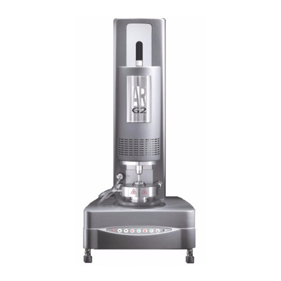
AR-G2/AR 2000ex/AR 1500ex
Rheometers
Getting Started Guide
Revision R
Issued January 2011
Table of
Contents
Previous
Page
Next
Page
1
2
3
4
5
Advertisement
Table of Contents
Need help?
Do you have a question about the AR-G2 and is the answer not in the manual?
Ask a question
Questions and answers
Related Manuals for TA AR-G2
Measuring Instruments TA DHR Series Getting Started Manual
Electrically heated plate (24 pages)
Measuring Instruments TA AR 2000ex Getting Started Manual
Rheometers (58 pages)
Measuring Instruments TA DHR Series Getting Started Manual
Discovery hybrid rheometer (58 pages)
Measuring Instruments TA CMI User Manual
(21 pages)
Measuring Instruments TA DISCOVERY DMA 850 Getting Started Manual
Dynamic mechanical analyzer (65 pages)
Measuring Instruments TA Q Series Getting Started Manual
Tma hermomechanical analyzer (58 pages)
Measuring Instruments TA DTC-300 Getting Started Manual
Thermal conductivity meter (55 pages)
Measuring Instruments TA PMG1 Installation, Commissioning & Operation
Pump/mixer assembly (24 pages)
This manual is also suitable for:
Ar 2000ex
Ar 1500ex
Table of Contents
Print
Rename the bookmark
Delete bookmark?
Delete from my manuals?
Login
Sign In
OR
Sign in with Facebook
Sign in with Google
Upload manual
Upload from disk
Upload from URL


Need help?
Do you have a question about the AR-G2 and is the answer not in the manual?
Questions and answers