Table of Contents
Advertisement
Quick Links
Advertisement
Table of Contents

Subscribe to Our Youtube Channel
Related Manuals for Balluff BNI IOL-104-000-K006


Summary of Contents for Balluff BNI IOL-104-000-K006
- Page 1 BNI IOL-104-000-K006 BNI IOL-102-000-K006 IO-Link Sensorhub digital User’s Guide...
-
Page 2: Table Of Contents
4.3. Parameter data / On-request data Inversion 40hex 4.4. Errors 4.5. Events Technical Data 5.1. Dimensions 5.2. Mechanical data 5.3. Electrical data 5.4. Operating conditions 5.5. Indicators / LEDs Module Status Digital Inputs Appendix 6.1. Type designation code 6.2. Order information www.balluff.com... -
Page 3: Notes To The User
Notes to the User 1.1. About this guide This guide describes the Balluff IO-Link sensor hub module. Connection to the host interface master is made through the IO-Link protocol. Functionally this compact, cost-effective module is comparable with a passive splitter box: It takes conventional sensor signals and passes them over the IO-Link interface. -
Page 4: Safety
Before maintenance, disconnect the device from the power supply. Note In the interests of product improvement, Balluff GmbH reserves the right to change the technical data of the product and the content of this manual at any time without notice. -
Page 5: Getting Started
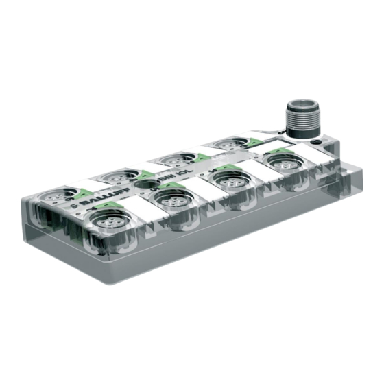
IO-Link Sensor-Hub BNI IOL-104-… / BNI IOL-102-… Getting Started 3.1. Connection overview BNI IOL-104-000-K006 9 Status LED „Power Supply“ 1 Mounting hole 2 IO-Link interface 10 Standard Input -Port 6 3 Status-LED: Input (Pin 2) 11 Standard Input -Port 4... - Page 6 11 Standard Input -Port 2 4 Status-LED: Input (Pin 4) 12 Standard Input -Port 0 5 Standard- Input -Port 3 13 Label 14 Status-LED “COM” 6 Standard- Input -Port 5 7 Standard- Input -Port 7 8 Status LED “Power Supply” www.balluff.com...
-
Page 7: Mechanical Connection
Note! A standard sensor cable is used for connecting to the host IO-Link Master. 3.5. Sensor interface Module-specific connection possibilities: Sensor-Hub Digital Input-Ports BNI IOL-104-000-K006 BNI IOL-102-000-K006 Standard input port (M12, A-coded, female) Function +24 V, max. 100 mA Input (only BNI IOL-104…) -
Page 8: Io-Link Interface
Data which is sent from Device to Master. Output data Data which is sent from Master to Device. Input data Byte *Only for BNI IOL-104-000-K006 There is no output data at BNI IOL-102-… and BNI IOL-104-… Output data 4.3. Parameter data / SPDU... -
Page 9: Inversion 40Hex
IO-Link Sensor-Hub BNI IOL-104-… / BNI IOL-102-… IO-Link Interface Inversion 40 Byte Index * Only for BNI IOL-104-000-K006 4.4. Errors Error Code Description 0x8011 Index not available 0x8012 Subindex not available 0x8030 Value out of range 4.5. Events Event Code... -
Page 10: Technical Data
≤ 40 mA Current draw without load 5.4. Operating -5 °C … +55 °C conditions Operating temperature -25 °C … +70 °C Storage temperature Immunity tests: EN 61000-6-2:2005 AC:2005 Emission tests: EN 61000-6-4:2007 A1:2011 Vibration/shock EN 60068 Part 2-6/27 www.balluff.com... -
Page 11: Indicators / Leds
LEDs are associated with the digital ports which indicate the operating states: LED 1 – Input pin 2 (only BNI IOL 104) LED 2 - Input pin 4 Signal Function Yellow Input signal = 1 Input signal = 0 www.balluff.com... -
Page 12: Appendix
Appendix 6.1. Type designation code BNI IOL-10x-000-K006 Balluff Network Interface IO-Link interface Functions 104 = 16 Inputs 0,1A 102 = 8 Inputs 0,1A Version 000 = Standard version Mechanical configuration K006 = Plastic housing Connectors: - BUS and Power Supply: 1x M12x1, external thread - Input-Ports: 8x M12x1, internal thread 6.2. - Page 13 IO-Link Sensor-Hub BNI IOL-104-… / BNI IOL-102-… Notes www.balluff.com...
- Page 14 Balluff GmbH Schurwaldstrasse 9 73765 Neuhausen a.d.F. Germany Tel. +49 7158 173-0 Fax +49 7158 5010 www.balluff.com balluff@balluff.de...
Need help?
Do you have a question about the BNI IOL-104-000-K006 and is the answer not in the manual?
Questions and answers