Table of Contents
Advertisement
Quick Links
Advertisement
Table of Contents

Subscribe to Our Youtube Channel
Related Manuals for Kobold NGM-HART


Summary of Contents for Kobold NGM-HART
- Page 1 Operating Instructions ® Configuration Set/HART -Modem Model: NGM-HART...
-
Page 2: Table Of Contents
Configuration Set NGM-HART We don’t accept warranty and liability claims neither upon this publication nor in case of improper treatment of the described products. The document may contain technical inaccuracies and typographical errors. The content will be revised on a regular basis. These changes will be implemented in later versions. -
Page 3: Note
Please read these operating instructions before unpacking and putting the unit into operation. Follow the instructions precisely as described herein. The instruction manuals on our website www.kobold.com are always for currently manufactured version of our products. Due to technical changes, the instruction manuals available online may not always correspond to the product version you have purchased. -
Page 4: Installation
- Excel-Configuration-Sheet „NGM configuration tool LA V177.xls” (since 01/2022) - DC supply 24V@30mA (for powering the NGM meter) - Kobold-HART-Modem with USB connector (Order code HARTCOMM) or any similar standard HART modems available on the market. - Communication resistor approx. 250 Ohm... -
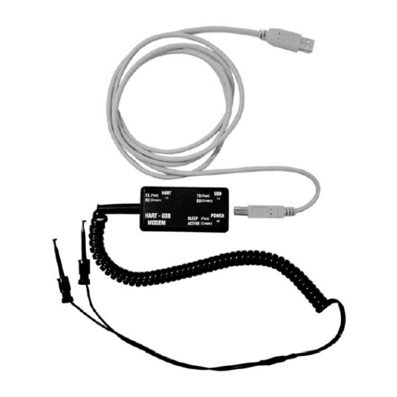
Page 5: Electrical Connection
Configuration Set NGM-HART Electrical connection ® The supplied HART modem must be connected on the device side via a current loop resistor (250 Ohm, in the scope of supply). On the PC side is a normal USB connection required. Figure 1... -
Page 6: Commissioning
Note 1! The current Excel file for configuring the NGM sensor, as well as the drivers for the modem, can also be downloaded from our homepage www.kobold.com, under Product search "NGM" / Downloads. Note 2! When using the configuration of the NGM with a HART modem, the baud rate of your USB communication "must"... - Page 7 Configuration Set NGM-HART 4.3.1 Connection of a NGM Probe to a PC ® • Check the COM port assignment of the PC to the USB HART modem with the Device Manager http://www.computerhope.com/issues/ch000833.htm ® * In this case COM port 4 has been assigned to the HART...
- Page 8 Configuration Set NGM-HART 4.3.2 First Steps with the Excel Tool Open the Excel file Prerequisite: worksheet is active and the macros are running (Hint: A restart of the Excel file might help to activate the Macros.) HOME Enter the assigned COM port indicated at the device manager.
-
Page 9: Configuration
Configuration Set NGM-HART 5. Configuration Basic Configuration ® Establishing a HART communication: • Serial number obtainable by clicking on the light blue SEND button J2 in step 1 “get serial number” • Macros are running • OK status (H2) disappears and reappears after serial number read out and... -
Page 10: Upper / Lower Range Value
Configuration Set NGM-HART Upper / Lower Range Value BASIC CONFIGURATION • Read out actual 4…20mA settings by clicking on I6 and I7 With the command “get lower / upper range value”, the actual 4…20 mA values in mm are shown after the OK status disappeared and is visible again. - Page 11 Configuration Set NGM-HART Reference point = 0 mm NGM-HART K05/0922 page 11...
-
Page 12: Response Time
Configuration Set NGM-HART Response Time BASIC CONFIGURATION • Read out actual response time, by clicking on I9. Field G9 is showing the actual response time multiplied with 0,1ms. • Change actual response time within a range of 2 … 100 (0,2 … 10 sec) in field G8 and clicking on I8 “set response time”. -
Page 13: Switching Output Mode
Configuration Set NGM-HART Switching Output Mode BASIC CONFIGURATION • Read out actual switching output mode by clicking on I11 Field G11 is showing the actual switching output mode. 0 = nc = normally closed 1 = no = normally open Once the probe is powered, the switch output can be open or closed. - Page 14 Configuration Set NGM-HART 5.4.1 Threshold switching output BASIC CONFIGURATION • Read out actual lower / upper threshold switching output, by clicking on I13 and I15. Field G13/15 indicates the actual lower / upper switching threshold. With the help of the thresholds, a hysteresis can be programmed to avoid output switching at turbulent levels.
- Page 15 Configuration Set NGM-HART 5.4.2 Upper Dead Band BASIC CONFIGURATION • Read out actual upper dead band, by clicking on I17. Field G17 indicates the actual upper dead band. With the upper dead band, noisy signals or ringing caused by the installation can be blocked.
- Page 16 Configuration Set NGM-HART 5.4.2 Amplitude threshold BASIC CONFIGURATION • Read out actual amplitude threshold, by clicking on I19 Field G19 indicates the actual amplitude threshold. Dynamic noise or ringing can be blocked if it is within the amplitude threshold band. The level reflection should be always 1/3 bigger than the width of the amplitude threshold band.
- Page 17 Configuration Set NGM-HART 5.4.3 Disturbance Signal Scan Status BASIC CONFIGURATION • Read out actual disturbance signal scan status by clicking on I21 Field G21 indicates the actual disturbance scan signal status. 00=off, raw echo curve 01=disturbance signal active on top ...
- Page 18 Configuration Set NGM-HART 5.4.4 Probe Type BASIC CONFIGURATION • Read out actual probe type status, by clicking on I24. Field G24 indicates the actual probe type status. 0= coaxial probe 1= single probe rod or rope Thresholds are adapted automatically by changing this parameter.
- Page 19 Configuration Set NGM-HART 5.4.5 Probe Length BASIC CONFIGURATION • Read out actual probe length, by clicking on I26. Field G26 indicates the actual probe length in mm. • Change actual probe length in field G25 and click on I25 “set probe length”.
- Page 20 Configuration Set NGM-HART 5.4.6 Set Delivery Configuration BASIC CONFIGURATION • Set actual parameters as delivery configuration by clicking on I27 Former delivery configuration parameters will be overwritten! No reset to factory conditions is possible anymore. UNDO NOT POSSIBLE! page 20...
- Page 21 Configuration Set NGM-HART 5.4.7 Reset to Delivery Configuration BASIC CONFIGURATION Reset unit back to delivery configuration, by clicking on I28. 4…20mA, response time, switching mode and thresholds, upper dead band, amplitude threshold, disturbance scan, probe type, and probe length will be set back to delivery configuration.
- Page 22 Configuration Set NGM-HART 5.4.8 Level Reading BASIC CONFIGURATION • Get actual level reading, by clicking on I29. If you do not measure the current output in series with a Multimeter, it is recommended to read out the level 3 – 5 times to recognize potential current fluctuations.
- Page 23 Configuration Set NGM-HART 5.4.9 Software Revision BASIC CONFIGURATION • Get actual software revision, by clicking on I30. You can get the actual softwaretool on our homepage https://www.kobold.com/ NGM-HART K05/0922 page 23...
- Page 24 Configuration Set NGM-HART 5.4.10 Device Status BASIC CONFIGURATION • Get actual devise status, by clicking on I31. Important probe status information can be communicated. Click on the small red upper right corner for more details. page 24 NGM-HART K05/0922...
- Page 25 Configuration Set NGM-HART 5.4.11 Signal Data – Echo Curve BASIC CONFIGURATION • Acquire actual signal data or also called echo curve by clicking on I32 Once the OK status in field H32 does not disappear anymore, the echo curve can be visualized by clicking on worksheet SIGNAL.
- Page 26 Configuration Set NGM-HART 5.4.12 Signal Range BASIC CONFIGURATION • Set signal range, by entering values in field G33/34 and clicking on I33/34 Depending on the probe length, the range within the echo curve in worksheet SIGNAL can be adapted. A negative X1 range of -1000 is always recommended and standard. With this the microwave generation and coupling can be verified.
- Page 27 Configuration Set NGM-HART 5.4.13 Signal SIGNAL • Visualization of the actual echo curve, where the level calculation is based on. • The NGM gets 70 echo curves every second for calculating the level. The most important parameters (4…20mA; dead band and amplitude threshold) are visualized.
- Page 28 Configuration Set NGM-HART 5.4.14 More Parameters… ADVANCED CONFIGURATION • Parameters within the worksheet ADVANCED CONFIGURATION are only recommended to change by experts. page 28 NGM-HART K05/0922...
- Page 29 Configuration Set NGM-HART 5.4.15 Signal Discussion 1 Empty Coaxial Probe • Nice reference reflection at the beginning • Perfect coupling into the coaxial probe • Positive end of probe reflection which corresponds to the physical end of probe Dead band parameter at 30 mm.
- Page 30 Configuration Set NGM-HART 5.4.16 Signal Discussion 2 Level Coaxial Probe • Stable reference reflection at the beginning • Negative level reflection at 168mm • No end of probe reflection as energy is completely reflected at water surface Dead band parameter at 30 mm.
- Page 31 Configuration Set NGM-HART 5.4.17 Signal Discussion 3 Empty Rod Probe • Nice reference reflection at the beginning • Strong positive impulse at the transition of coupling to the single rod • Reflection can change with mounting conditions. • Positive end of probe reflection which corresponds to the physical end of probe Dead band parameter at 30mm.
- Page 32 Configuration Set NGM-HART 5.4.18 Signal Discussion 4 Level Rod Probe • Stable reference reflection at the beginning • Negative level reflection at 168mm • No end of probe reflection as energy is completely reflected at water surface • Positive coupling reflection in saturation as amplification factor increased Dead band parameter at 30 mm.
-
Page 33: Technical Data
Configuration Set NGM-HART 6. Technical Data Operating temperature -25 °C… +55 °C Enclosure Polystyrene Connection to PC USB 1.1 “B” connector Cable to PC USB “A-B” 1.8 m Connection to HART filed KLEPS 2 Spiral cable length 0.6 m (1.1 m) -
Page 34: Disposal
Configuration Set NGM-HART 7. Disposal Note! Avoid environmental damage caused by media-contaminated parts Dispose of the device and packaging in an environmentally friendly manner Comply with applicable national and international disposal regulations and environmental regulations. Batteries Batteries containing pollutants are marked with a sign consisting of a crossed-out...
Need help?
Do you have a question about the NGM-HART and is the answer not in the manual?
Questions and answers