Riden RD6006 Instructions Manual
Constant voltage and constant current dc power supply
Hide thumbs
Also See for RD6006:
- Instruction (25 pages) ,
- Manual (77 pages) ,
- Instruction manual (68 pages)
Chapters
Table of Contents

Subscribe to Our Youtube Channel
Related Manuals for Riden RD6006


Summary of Contents for Riden RD6006
- Page 1 恒压恒流数控电源使用说明 Constant Voltage and Constant Current DC Power Supply Instruction 型号: RD6006-W/ RD6012-W/ RD6018-W/ RD6024-W /RD6006P-W /RD6012P-W Model: RD6006/ RD6012/ RD6018/ RD6024/RD6006P/RD6012P 修订时间 2022.10.15 点击进入 CLICK VIEW...
- Page 2 恒压恒流数控电源操作手册 型号: RD6006-W/ RD6012-W/ RD6018-W/ RD6024-W /RD6006P-W /RD6012P-W 修订时间:2022.10.15 尊敬的用户, 感谢您购买由杭州睿登科技有限公司出品的恒压恒流数控电源, 为了让您更 快了解本产品的全部功能,获得更好的使用体验,避免出现误操作,使用前请仔细阅读本说明 并保留好,以便日后查阅。本手册为完整版说明书。 本说明书对应固件版本 RD6006-W(V1.38), RD6012-W(V1.35), RD6018-W(V1.37), RD6024-W(V1.37), RD6006P-W(V1.41),RD6012P-W(V1.44)不同固件版本下,界面或操作可能 会有不同,使用时请注意。建议升级为最新固件,获取更好的使用体验。 - 1 -...
-
Page 3: Table Of Contents
目录 1.1 配件清单 ................................4 1.2 产品技术指标 ..............................4 1.3 面板说明 ................................5 1.3.1 前面板 ................................. 5 1.3.2 后面板 ................................. 6 1.4 操作说明 ................................6 1.4.1 主界面 ................................. 6 1.4.2 操作说明 ..............................7 1.4.2.1 电池充电功能说明..............................8 1.4.2.2 主界面电压电流设置 .............................. 8 1.4.2.3 快捷存储和调出... - Page 4 4.1.2 安装软件 ..............................22 4.2 软件的使用 ................................22 4.2.1 上位机联机..............................22 4.2.2 软件使用介绍 .............................23 4.3 功能介绍 ................................24 4.3.1 基础功能 ..............................25 4.3.2 校准微调 ..............................25 4.3.3 高级功能 ..............................26 4.3.4 RS485 多机通信 ............................26 4.3.4 固件升级 ..............................27 4.3.5 开机图片更新 .............................28 4.3.6 软件更新 ..............................29 4.3.6 语言的选择..............................29 4.3.7 关于 ................................30 附录...
-
Page 5: 配件清单
1.1 配件清单 RD 数控电源主机一台 X25A 输出线一套 输入电源线一条 Micro 通信线一条(X25A 包装内) 外置温度传感器一条 10K B3950 备用保险丝一只 1.2 产品技术指标 RD6006- RD6012- 产品型号 RD6018-W RD6024-W RD6006P-W RD6012P-W 电压电流位数 四位 五位 输出电压范围 0-60V 输出电流范围 0-6A 0-12A 0-18A 0-24A 0-6A 0-12A 0-1140 输出功率范围 0-360W 0-720W 0-1080W... -
Page 6: 面板说明
100mV 输出纹波典型值 @12A ② 20mV 100mV 250mV@6A (VPP) 150mV @24A 产品工作温度范围 -10℃~40℃ 外置温度传感器测量范 -10℃~100℃/0℉~200℉ 围 外置温度传感器测量误 ± 3℃/± 6℉ 差 恒压模式响应时间 2ms(0.1A-5A 负载) 恒压模式负载调整率 ± (0.1%+2 个字) 恒流模式负载调整率 ± (0.1%+3 个字) 容量测量范围 0-9999.99Ah 能量测量范围 0-9999.99Wh 容量能量记录误差 ±2% 输出电压> 40V 或输 出电流>4A 输出电流>8A 或... -
Page 7: 后面板
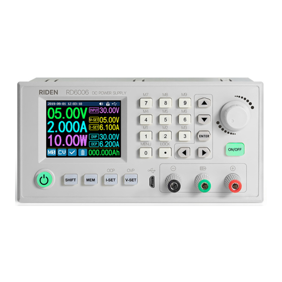
A:电源开关 B:SHIFT 第二功能键 C:快捷存储键 D:输出电流/过流保护设置 E:输出电压/过压保护设置 F:micro USB 通信接口 G:电源输出负极/电池充电负极 H:电池充电正极(充电专用端子) I:电源输出正极 J:输出开关键 K:ENTER/确认键 L:编码电位器(旋转)/返回键(按动) M:方向键 N:数字键盘 O:显示屏幕 0 1.3.2 后面板 P:输入电源接口 Q:开关 R:外置温度传感器接口 S:散热孔 1.4 操作说明 上电后首先显示开机图片,然后进入主界面。 1.4.1 主界面... -
Page 8: 操作说明
AA:输出电压回读值 AB:输出电流回读值 AC:输出功率显示值 AD:当前数据组指示 AE:恒压恒流状态指示 AF:保护状态指示 AG:电池充电状态指示 AH:循环显示区 AI:输出过流保护设定值 AJ:输出过压保护设定值 AK:输出电流设定值 AL:输出电压设定值 AM:输入电压 AN:当前通信模式指示 AO:按键状态指示 AP:按键声音状态指示 AQ:电流量程指示(仅 RD6012P-W 有此选项) AR: 日期时间 经典风格 详细风格 曲线风格 主界面按动 或 键可以在经典风格、详细风格、曲线风格中切换,曲线风格下,旋转编 码电位器可以缩放曲线纵坐标, 按动 键可以开始或暂停曲线显示; 主界面调整风格状态后 不记忆,如需设置默认启动界面风格请前往 1.4.2.6 主界面风格设置。 1.4.2 操作说明 菜单操作中,红色、光标处或反显处为当前选中菜单,按动 键确认或进入,按动编码 电位器返回,按动方向键移动光标或菜单翻页,旋转编码电位器更改设置,菜单中返回时自动... -
Page 9: 电池充电功能说明
保存设置。按住 键上电恢复出厂设置,按住 键上电恢复出厂校准值,按住 键上电 进入 boot 模式。 1.4.2.1 电池充电功能说明 电池充电操作说明视频: https://qr17.cn/E78wfT 上电后,循环显示区处,外置温度传感器温度、容量、能量循环切换显示,电源输出时, 容量、能量自动累计,关机清零。 电池充电正极接电池正极,电源输出负极接电池负极,正确连接电池后电池充电状态指示 提示电池接好, 设定好电压电流后然后按 键开始充电, 同时电池充电状态指示 提示, 当输出电流小于充电截止电流(10mA 可设定)或外置温度传感器测量温度大于充电截止温度时 自动关闭输出。 当使用带异口保护板的电池需要使用电源输出正极和电源输出负极充电, 电池 充电时的电压电流需要自行设定。 强烈建议使用原装充电器给电池充电,本机充电功能仅能起临时替代作用,只有详细了解 电池参数才可以充电,错误设置会损害电池寿命甚至起火爆炸。 1.4.2.2 主界面电压电流设置 主界面电压电流设置操作说明视频: https://qr17.cn/CpZUhq 按动 或 键可以在 6A、12A 两个电流量程指示中切换(仅限 RD6012P-W), 切换量程时 会自动关闭输出。按动 键设定输出电流设定值,转动编码电位器时设定值立刻生效,旋转 调整不会超过限制,按动... -
Page 10: 快捷存储和调出
电流回读值大于输出过流保护设定值(OCP)后,电源自动关闭输出,并 提示,当输出电压回 读值大于输出过压保护设定值(OVP)后, 电源自动关闭输出, 并 提示, 当系统温度大于 80℃, 电源自动关闭输出,并 提示。 1.4.2.3 快捷存储和调出 快捷存储调出操作说明视频:https://qr17.cn/ACO2oQ 按动 +数字键盘 1-9,可以将当前输出电压设定值、输出电 流设定值、输出过压保护设定值、输出过流保护设定值、电流量 图二 程指示存储为快捷调用(如图二),按动 键确认,左下角当前 数据组指示 提示,按动编码电位器或按 键选中“取消”后 按 键取消,再次手动改变设置值后变为 提示。 按动 +数字键盘 1-9 可以快捷调出存储的数值(如图三)按动 键确认后输出电压设定值、输出电流设定值、输出过压保护 图三 设定值、输出过流保护设定值、电流量程指示修改,左下角当前数据组指示 提示,再次手动 改变设置值后变为 提示。 在系统设置菜单中关闭调出确认后, 不弹出窗口, 直接修改设置值。 为上电默认数据组,按键修改设定后按 键或旋转编码电位器更改设定后按编码电... - Page 11 动 或 键进入子菜单,蓝色底色为子菜单选中位置,旋转编码电位器改变设置,按动编 码电位器返回,此时按动 或 键可以切换主菜单。 按动 键进入系统设置主菜单,按动 或 键进入 子菜单。 子菜单:(如图五) Settings 系统语言默认为英文,也可以简体中文、法语、德语、俄语中选 图五 择; 调出确认默认打开,快捷调出时会先弹出窗口,关闭后快捷调出时直接更改设置值; 调出输出默认关闭,快捷调出时关闭输出,打开后,快捷调出后自动打开输出; 开机输出默认关闭,开机时输出为关闭,打开后开机自动打开输出; 开机图片默认打开,开机后会首先加载开机图片,然后进入主界面,关闭后开机直接进入主界 面; 按键声音默认打开,按键声音状态指示 提示,按动按键会有短促的滴滴声,关闭后,按键 声音状态指示 提示,按键静音; 背光亮度默认为 4,可以在 0-5 之间设置; 测量速度默认为低,可以设置低中高三档,对应的是输出电压电 流实际值的刷新率; 最大功率默认为 740W,可以在 0-740W 之间设置,对应可以设置 图六 的最大功率, 右上角图标*1 为调整倍率, 可以通过按动 或...
-
Page 12: 主界面风格设置
子菜单:(如图八) Communication 通信接口默认为 USB,也可以在 WIFI、TTL、RS485 中切换,USB 指 micro USB 通信接口,设置后当前通信模式指示 提示,与 PC 上位机通信时 提示;设置 WIFI 后当前通信模式指示 提示, 与 APP 或 PC 上位机通信时 提示;TTL 功能暂未开放,RS485 需 要更换 485 模块,设置后当前通信模式指示 提示,通信时 提 示; 图八 设备地址默认为 001,可以在 001-255 之间选择;通信速率和设备 地址必须和上位机和手机 APP 保持一致。通信功能具体详见完整 版说明书中上位机和 APP 中连机部分。 子菜单:(如图九) Date and Time 日期和时间可以在... -
Page 13: 快捷数据组设置
置、过压设置、过流设置、容量累计、能量累计、电池电压、电池温度中每个独立的项目可以 设置单独的颜色,颜色可以在红、绿、蓝、白、黄、品红、青色、浅蓝、灰色、棕色、橙色、 黄绿色、蓝绿色、粉色、栗色十五个颜色中选择,改变设置后, 打开自定义颜色,就可以开启(如图十三)。 1.4.2.7 快捷数据组设置 存储数据设置操作说明视频: https://qr17.cn/CKqPcj 主界面下按动 键进入系统设置菜单,然后再按动两次 图十三 键进入(如图十四)存储设置主菜单: 按动 键进入菜单, 按动方向键可以选择数据组, 此时旋转 编码电位器可以在 6A、12A 两个电流量程指示中切换(仅限 RD6012P-W),选择好量程后再设置参数。按动 键设定存储数 据的输出电流设定值,转动编码电位器可以直接调整,旋转调整 图十四 不会超过限制, 按动 或 键可以更改光标位置, 也可以直接使 用数字键盘输入按 键确认。如输入错误,可以按动编码电位器取消。 按动 键可以设定存储数据的输出电压设定值,方法类似输出电流设定值操作。 先按 键或 键可以设定存储数据的输出过流保护设定值或输出过压保护设 定值,方法类似输出电流设置。 数据设定完成后,按动编码电位器返回并保存数据。 1.4.2.8 系统信息 主界面下按动 键进入系统设置菜单,然后再按动三次... -
Page 14: 安卓手机 App 使用说明
安卓手机 App 使用说明 2.1 手机 App 软件安装 本软件仅支持 Android5.0-Android12.0 系统使用,如必须使用软件功能,请先预装测试。软 件使用 WiFi 功能,需申请定位服务,请同意并打开定位,手机 App 请从文件管理器中打开安 装。WiFi 模块不能在带电状态下插拔,会导致损坏。本说明书对应软件版本 1.0.12,不同版本 会稍有不同,建议升级为最新软件,获取更好的使用体验。 2.1.1App 的下载 RD6012P 数控电源资料官网下载链: http://www.ruidengkeji.com/ziliaoxiazai 国内用户需通过浏览器直接下载到电脑,解压后将 apk 文件通过手机助手或者文件管理器 导入到手机目录中,然后手机文件管理器中打开 apk 文件。可以使用谷歌 play 的用户请通过 谷歌 play 搜索如不会下载或无法下载可以找客服人员索取下载链接。 2.2 安装完成 安卓 App 安装联机过程视频:https://qr17.cn/CYCT10 WiFi 联网等帮助说明:(配网不成功的,都戳这里)... - Page 15 BA:侧边栏 BQ:向左移动光标 BB:添加 BR:向右移动光标 BC:返回 BS:设置 BD:更多选项 BT:亮度 BE:曲线图 BU:系统温度 BF:输出电压实际值 BV:同步时间 BG 输出电流实际值 BW:快捷调出 BH:输出功率实际值 BX:电池电压 BI:输入电压实际值 BY:外接传感器温度 BJ:输出电压设定值 BZ:开机累计输出能量 BK: 输出电流设定值 CA:开机累计输出容量 BL:ON/OFF 开关 CB:量程切换 BM:状态指示 CC:当前产品型号 BN:键盘锁定指示 CD:产品序列号 BO:恒压/恒流状态指示 CE:固件版本 BP:调整轮...
-
Page 16: 3App 的使用
3.2.3APP 的使用 安 卓 App 操 作 过 程 视 频 : https://qr17.cn/A6C1ni 3.2.3.1 智能配网 初次 WiFi 联网,先将 RD6012P 的 图十六 图十九 WiFi 模块插好, 然后给 RD6012P 供电, WiFi 模块的蓝灯会闪烁一下。在系统设置中将通信接口设置为 WiFi 后重启 RD6012P,然后将 RD6012P 和手机都放置在靠近 2.4G 路由器的地方(此时手机也必须在同一个 2.4G 网络下,路 由器关闭 AP 隔离和 WMM 功能),RD6012P 会等待手机连接(如图十六)。手机按(如图十七) 中... -
Page 17: 正常联网
图二十 如果配网失败,请给模块断电,重新操作一次(多次联网失败仔细观看联机过程视频并尝 试用手机分享 WiFi 热点测试)。 华为手机请关闭随机 MAC, 否则每次连接 WiFi 需要重新配网: https://jingyan.baidu.com/article/a681b0decb7c4b7a18434683.html 3.2.3.2 正常联网 RD6012P 启动后, 会先连接 WiFi, 然后检测手机 APP 是否能连通, 锁屏或 APP 后台运行时, 可能会无法连接,如果手机的 IP 地址发生变更需要先按 键然后按 键重置网络,再次执 行 3.2.3.1 智能配网过程。建议通过路由器设置手机 MAC 地址绑定 IP。 3.2.3.3APP 操作 安卓 APP 操作过程视频 : 暂无 点击... - Page 18 小时的文件。 注:1:因安卓手机种类繁多,因此在个别品牌或者一种品牌的不同比例屏幕上 UI 界面显示不 一样。 2:应用程序权限要求,允许程序安装时必要权限(允许后台运行,允许使用蓝牙,允许操作文 件夹, 允许读取应用列表等)而且在安装完毕后还要在手机中设置程序的权限: 允许后台运行、 锁屏不清理、允许自启动等(持续记录数据时防止系统强制退出 APP)。...
-
Page 19: 苹果手机 App 使用说明
苹果手机 APP 使用说明 3.1 手机 APP 软件安装 3.1.1APP 的下载 苹果 APP 仅支持 IOS10.0-14.3,iphone6 以上机型,在苹果商店搜索“RDPower”下载。如 必须使用软件功能,请先预装测试。软件使用 WiFi 功能,需申请定位服务,请同意并在设置- 隐私中打开定位。 本说明书对应软件版本 1.1.16, 建议升级为最新软件, 获取更好的使用体验。 3.2 安装使用 首次启动软件,系统可能会申请定位(如图二十一),选择“使用 APP 时允许”,软件运行 时会申请使用数据(如图二十二),选择“无线局域网与蜂窝移动网络”。 图二十一 图二十二... -
Page 20: 软件更新
苹果 APP 安装联机过程视频:https://qr17.cn/CABSZI 安装完成,手机 APP 图标如图: 3.2.1 软件更新 您可从苹果商店获取最新的软件,当软件有更新时,打开后会提示版本更新。 3.2.2APP 界面显示 打开后界面显示下图 DA:连接/断开 DO:系统温度 DB:导出曲线数据 DP:数据快捷调出 DC:曲线图 DQ:同步时间 DD:输出电压实际值 DR:电池电压 DE:输出电流实际值 DS:外接传感器温度 DF:输出功率实际值 DT:开机后输出容量 DG:输入电压测量值 DU:开机后输出能量 DH:输出电压设定值 DV:产品型号 DI:输出电流设定值 DW:产品序列号 DJ:输出开关按钮 DX:产品固件版本 DK:保护状态指示 DY:量程切换 DL:电池充电指示 DZ:主界面 DM:恒压恒流状态 EA:配网界面 DN:屏幕背光亮度 EB:个人中心 3.2.3APP 的使用... -
Page 21: 正常联网
下,路由器关闭 AP 隔离 WMM 功能),RD6012P 会等待手机连接(如图二十三)。点击 EA 打开 “智能配网”界面(如图二十四),并输入无线密码。点击“初始化”,等待约 20 秒, 图二十四 图二十五 RD6012P 会获取手机的 IP 地址(如图二十六)。 然后(如图二十五) 点击配置网络,等待约 30 秒,APP 显示连接成功,RD6012P 正常 启动,配网成功,返回到主界面后点击 DA“连接”即可连接。 如果配网失败,请给模块断电,重新操作一次(多次联网失败 仔细观看联机过程视频并尝试用手机分享 WiFi 热点测试)。 图二十六 3.2.3.2 正常联网 RD6012P 启动后,会先连接 WiFi,然后检测手机 APP 是否能连通,如果手机锁屏或 APP 不 在前台运行下,会无法连接;如果手机的 IP 地址发生变更需要先按左键然后按 键重置网... - Page 22 点击 DH 或 DI 的输入框,输入数值设定电压电流,点击空白处返回,超出的值不能设定。 点击 DB 可以将电压电流曲线导出成表格文件并分享到其他应用,最长可以记录 24 小时的文 件。 点击 EB 可以设置软件语言或者获取使用帮助。...
-
Page 23: 上位机软件的安装使用说明
4.1 软件安装 上位机安装视频:https://qr17.cn/ETUcEe 4.1.1 解压文件 首次使用先安装驱动程序, 打开 CH341SER 安装驱动, 然后用 microUSB 线插上 RD6012 等待电脑安装驱动完成。 4.1.2 安装软件 将压缩包解压到电脑 D 盘中,首先运行 Net framework4.7.2.exe 安装.net 环境,然后直接 运行 RidenPowerSupply.exe 上位机软件。文件夹其他文件运行所需,不要删除。 4.2 软件的使用 4.2.1 上位机联机 双击桌面上的图标“Riden Power Supply”就可以打开上位机软件。 WIFI 联机仅支持 RD6012P-W,WiFi 联机为测试功能,由于部分电脑的兼容性不好,无法连 接的请忽略。此功能不做任何保证,我们也将根据客户反馈结果决定是否保留。 电脑 WiFi 联机视频:https://qr17.cn/ByDJPj... -
Page 24: 软件使用介绍
将 RD6012P 通信接口设置成 WiFi,并重启,RD6012P 显示(如 图二十七),在上位机上点击“WiFi 配网”弹出 WIFI 配网界面(如 图二十九),点击“初始化”等待约 5-10 秒,RD6012P 显示本机 IP 地址后(如图二十八,点击“下一步”并输入 WiFi 名称和密码,然 后点击“配网”,等待约 20 秒,上位机提示连接成功,然后单击 图二十七 “联机”即可。 USB 联机:RD6012P 通信接口设置成 USB,用 MicroUSB 线把 RD6012P 与上位机连接好,打开上位机,上位机提示串口更新, 点击“联机”即可。 4.2.2 软件使用介绍 上位机使用视频:https://qr17.cn/EF1ZdQ 图二十八 图二十九 选择好通信端口、波特率、从机地址(默认为 001),点击“联机”开始通信,联机成 功后会自动锁定数控电源按键, 意外断开 3 秒后电源按键自动解锁, 同时 “联机” 按钮变为 “断 开”;点击“打开”可以打开数控电源输出,同时按钮变为“关闭”。... -
Page 25: 功能介绍
功能介绍 上位机软件界面主要有基础功能、固件升级、Logo 升级、检查版本更新及语言的选择等。 FA: 电压电流曲线 FB: 电池信息/快捷调出 FC: 校准微调 FD: RD/DPS 系列切换 FE: 语言选择 FF: 软件更新 FG: 关于 FH: 输入电压 FI: 输出电压实际值 FJ: 输出电流实际值 FK: 输出功率实际值 FL: 系统温度(摄氏度) FM: 系统温度(华氏度) FN: 恒压恒流状态... -
Page 26: 基础功能
FO: 保护状态 FP: 背光亮度 同步系统时间至 RD6012P FR: 输出电流设定值 FS: 量程切换 FT: 输出电压设定值 FU: 固件版本 FV: 序列号 FW: 产品型号 4.3.1 基础功能 上位机的基础功能包括:电压电流的设置、快捷输出、校准微调、亮度调节及电压电流曲 线导出,调整旋钮或输入数字可以改变设置电压电流, 按钮上方图表会显示实时的电压电流曲 线。在曲线图上滚动滚轮可以实现缩放,双击曲线自适应,右键可以清除曲线或者将曲线导出 成图片或 excel。 4.3.2 校准微调 校准微调需要拥有六位半以上的万用表的专业电子人士操作;校准微调会改变系统设置, 误操作可能会超出硬件极限值导致损坏,由此导致的损坏不纳入保修范围! 产品的极限误差一 般会比标称误差小很多,当误差接近甚至大于标称误差时,请首先确认测量仪器是否准确。 点击校准微调输入密码“168168”可以进入校准微调界面或者保存校准微调数据(输入此密码 即代表接受上述红字协议),联机后读取校准数据,通过点击箭头实现微调数值。根据一次函 数 y=kx+b,常数 b 相当于零点值,斜率 k 相当于比例值,调整这两个数值就能尽量去接近实际 测量的数值。... -
Page 27: 高级功能
校准微调操作视频:https://qr17.cn/DoPeBD 将输出电压设置为 1V,调整电压输出零点使万用表显示接近 1V,将输出电压设置为 30V (半量程) , 调整输出电压比例值使万用表显示值接近 30V; 同理设置为 0.1A 和 3A (半量程) 可以校准电流输出零点和电流输出比例;将输出电压设置为 1V 调整回读电压零点使 RD6012P 显示电压值与万用表测量值一致,同理设置 30V 可以校准回读电压比例值,同理设置为 0.1A 和 3A 可以校准电流回读零点和电流回读比例。RD6012P 的 6A 和 12A 为两个电流量程,需要 分开校准, 更改量程为 12A 然后设置 0.1A 和 6A 校准 12A 量程电流 (此部分不提供技术支持,... -
Page 28: 固件升级
时间,最长不长于 11 秒。 4.3.4 固件升级 固件升级操作视频:https://qr17.cn/BMFDds 首先按住 键给 RD6012P 供电,进入 boot 模式,连接好电脑,待模式信息中提示产品 为 boot 模式后点击“固件升级”,弹出固件升级提示框,然后点击“立即升级”即可(可以在 正常模式下升级,如果不能正常启动时,必须进入 Boot 模式升级,WiFi 下暂时未开放固件升 级)。 固件升级过程中,界面显示如下:... -
Page 29: 开机图片更新
4.3.5 开机图片更新 开机图片更新操作视频:https://qr17.cn/Bk2WXe 点击“开机图片更新”,弹出升级提示框,点击“选择图片”,(安装包内提供了一些 Logo 样张可以测试),点击“图片导入”即可,更新完成会自动重启。... -
Page 30: 软件更新
4.3.6 软件更新 点击 FF,系统会自动后台检测是否有新版本,如有新版本会弹框提醒更新。 4.3.6 语言的选择 点击 FE,可以设置中文、英文、法语、德语四种语言。... - Page 31 4.3.7 关于 点击 FG,可查看当前版本号、发布时间及版权信息等。...
-
Page 32: 附录 1:中文版本更新说明
附录 附录 1:中文版本更新说明 2021-10-15:中文第一版 附录 2:常见电芯电压对照 下列电压仅供参考,实际以电芯厂家提供参数为准。 电池种类 标称电压(V) 充电截止电压(V) 放电截止电压(V) 应用 特点 三元锂电 数码设备 容量大 电动车 磷酸铁锂 3.65 价格低 电动工具 铅酸电池 14.4 10.5 汽车/电动车 价格实惠,有铅污染 价格实惠,应用广泛, 干电池 不可充电 遥控器/时钟 不可充电 价格实惠 镍铬电池 1.25 玩具 有记忆效应 镍氢电池 玩具/剃须刀 无记忆效应 附录 3:常见电动车自行车电池电压对照表 下列电压仅供参考,实际以电池厂家提供参数为准。... -
Page 33: Constant Voltage And Constant Current
Please read this instruction carefully before using it. Keep it for future reference. This manual is suitable for RD series assembled set users. Note: This instruction is corresponding to RD6006(V1.38), RD6012(V1.35), RD6018(V1.37), RD6024(V1.37),RD6006P(V1.41), RD6012P(V1.44) the page and operation may be different under different firmware versions, please pay attention when using it. - Page 34 Content CONSTANT VOLTAGE AND CONSTANT CURRENT ......................32 DC POWER SUPPLY INSTRUCTION ..........................32 1.1 A ..............................35 CCESSORY 1.2 T ............................35 ECHNICAL ARAMETER 1.3 P ..............................37 ANEL NSTRUCTION 1.3.1 Front Panel ..............................37 1.3.2 Back Panel ..............................38 1.4 O ............................38 PERATION NSTRUCTION 1.4.1 Main Page ..............................38 1.4.2 Operation Introduction ..........................39 1.4.2.1 Battery Charging Function Introduction ........................
- Page 35 PC SOFTWARE INSTALLATION AND OPERATION INSTRUCTION ..................55 4.1 S ............................55 OFTWARE OWNLOAD 4.1.1 Unzip Files ..............................55 4.1.2 Unzip Files ..............................55 4.2 S .............................55 OFTWARE PERATION 4.2.1 Software Connection ...........................55 4.2.2 PC Software Operation Instruction .......................56 4.3 F ............................57 UNCTIONS NTRODUCTION 4.3.1 Basic Functions ............................58 4.3.2 Calibration ..............................59 4.3.3 Advanced Function ............................59...
-
Page 36: Accessory List
RD power supply*1 X25A output cable*1 Micro Communication cable*1 Input AC Power Cord*1(AC cord in kind prevail) (inside X25A bag) External Temperature Sensor*1 Backup Fuse*1 1.2 Technical Parameter Model RD6006 RD6012 RD6018 RD6024 RD6006P RD6012P Output voltage range 0-60.00V 0-60.000V Output current range 0-6.000A... - Page 37 Input voltage accuracy ±(1%+5 digits) ① Output voltage accuracy ±(0.3%+3 digits) ±(0.5‰+4 digits) Model RD6006 RD6012 RD6018 RD6024 RD6006P RD6012P Output current accuracy ±(0.5%+5 digits) ±(1‰+6 digits) Battery voltage accuracy ±(0.5%+3 digits) Default battery charging 10mA 100mA 10mA cutoff current Output ripple typical 100mV@12A;...
-
Page 38: Panel Instruction
Over temperature System temperature >80℃ protection Screen brightness setting 0-5(6 level) Screen 2.4 inch color HD display N.W. 2.4 kg 2.8kg 3.1 kg 3.1 kg 2.4 kg 2.8kg Product dimension About 17.3*9.2*33.6 cm (cm) USB communication WiFi communication ①:Accuracy test method:1 digit is the minimum resolution, so the error under 5V is ±(5*0.5‰+4*0.001)=±0.0065V. ②:Ripple measurement method: noise and ripple are measured at X1 range, AC coupling, 20 MHz of bandwidth on your oscilloscope with a 0.1uF parallel capacitor at the output terminals, pure resistor as load. -
Page 39: Back Panel
1.3.2 Back Panel P: Input power socket Q: Rocker switch R: External temperature sensor socket S: Heat dissipation holes 1.4 Operation Instruction After power-on, it will show boot image first, and then enters the main page. 1.4.1 Main Page AA: Actual output voltage value AB: Actual output current value AC: Output power AD: Current data group... -
Page 40: Operation Introduction
Traditional Style Detail Style Curve Style At main page you can press button to change the display style between Traditional Style, Detail Style and Curve Style, the display style will not be saved automatically, you need to set default Home Style at section 1.4.2.6 Main Page Style Setting. -
Page 41: Main Page Output Voltage And Current Setting
off current value (10 mA, can be set by user), or the temperature that the external temperature sensor tested is greater than the cut off temperature value, the output will be cut off automatically. Battery with protection board needs to be charged with red and black terminals. The charging voltage and current should be set on your own. -
Page 42: Data Group Quick Storage And Call Out
status indication, when the actual output current value is higher than the OCP value, the output will be cut off automatically, and show , when the actual output voltage value is higher than the OVP value, the output will be cut off automatically, and show , when the system temperature is higher than 80℃, the output will be cut off automatically, and show 1.4.2.3 Data Group Quick Storage and Call out... -
Page 43: System Setting
when communication starts, there will be displayed on the top (cannot unlock manually), at this time, the power button can be used, pressing other button will show(as shown in Figure 4), the keypad will be automatically unlocked after 3 seconds when the connection disconnected, there will displayed. - Page 44 output voltage and current. Max Power is set to 740W by default, you can set it between 0-740W, it is the max output power. On the top you can see the *1 icon, it is the adjustment magnification, you can press magnification so that you can set the value quickly, choose the different Figure 6...
-
Page 45: Main Page Display Style Setting
Address is set to 001 by default, you can set it between 001 and 255; The Baud rate and address on the device should be same with the information on PC software or APP. You can see more communication at PC software and APP section. Figure 9 Date and Time Sub-Menu( Figure 9... -
Page 46: Storage Data Setting
1.4.2.7 Storage Data Setting Data group setting in manual operation video: https://drive.google.com/drive/folders/13APYtlRAaMcKmStbW M8toB8oOW5wi4ph?usp=sharing You can press to enter the system setting menu, and then press button twice to enter the data storage setting Figure 13 menu(as shown in Figure 14). Press the Enter button to enter the sub-menu, press the direction button to choose the data group, you can rotate the encoder potentiometer to switch 6A and 12A range(only for RD6012P... -
Page 47: Android App Instruction
Android APP Instruction 2.1 Mobile Phone APP Installation Only RD6012P-W supports WIFI connection. If you want to use the APP, you need to order a WiFi board. This App only supports Android 5.0 to Android 10.0 operating system, and there may be incompatibilities problems between APP and operating system, please install and test the software before buying the product. -
Page 48: App Operation
BA: sidebar BQ: move the cursor to the left BB: add device BR: move the cursor to the right BC: return BS: set button BD: more options BT: screen brightness BE: curve BU: system temperature BF: actual output voltage BV: sync time BG: actual output current BW: data group quick call out BH: actual output power... - Page 49 RD6012P will wait for the phone to connect as shown in Figure 16. Press “BA” (add device) and choose “RD power series”, it will show like Figure 17, then enter the WiFi password and confirm you are using 2.4G network as shown in Figure 18.
-
Page 50: Proper Wi-Fi Connection
figure 20 If the distribution network fails, please power off the module and re-operate in the same way (multiple networking failures you can watch the video and try to use the hotspot of the mobile phone to test). If you use Huawei brand phone, please turn off the random MAC address function. 3.2.3.2 Proper Wi-Fi Connection When power on RD6012P, it will connect Wi-Fi first, and then detect if it can be connected to APP, and it may not be connected successfully if the phone is under screen-lock status or the APP is... - Page 51 1. There are many kinds of Android phone, so the user interfaces maybe different on some brand phones or different scales of the same brand. 2. Application permission requirements, allow the necessary permissions when the APP is installed (allow background running, using Bluetooth, operation on the folder, reading the application list, etc.) and also set the permissions of the APP after installation: Allow background running, never shut down when lock screen, allow self-starting (it is used to prevent the system from forcibly exiting the APP when recording data), etc.
-
Page 52: Ios App Instruction
IOS APP Instruction 3.1 Mobile Phone APP Installation WiFi connection only supported for RD6012P-W. If you want to use the APP, you need to order a WiFi board. 3.1.1 APP Download Apple APP only supports IOS10.0-14.3, iphone6 and above models, search for "RDPower" in the Apple store to download. -
Page 53: App Update
When Figure 21 Figure 22 Figure 21 software is started for the first time, the system may apply for positioning (as shown in ), select Figure 22 "Allow when using APP", and apply for data when the software is running (as shown in ), select "Wireless LAN and cellular mobile network". - Page 54 then power on RD6012P, you will see the blue LED blinks once. Set the communication interface to WIFI, restart RD6012P, then place the RD6012P and the mobile phone close to the 2.4G router (the mobile phone must also be under the same 2.4G network, and the router must disable the AP isolation function and the WMM function).
-
Page 55: Proper Wi-Fi Connection
3.2.3.2 Proper Wi-Fi Connection When power on RD6012P, it will connect Wi-Fi first, and then detect if it can be connected to APP, and it may not be connected successfully if the phone is under screen-lock status or the APP is running at the background. -
Page 56: Pc Software Installation And Operation Instruction
PC Software Installation and Operation Instruction Requirement: Win 7-Win10 system and the computer has Internet connection. This PC software is designed by Hangzhou Ruideng technology CO., LTD, it has no virus, if your anti-virus software prompts for a virus warning, please allow all its features, otherwise it will affect the normal operation of the software. -
Page 57: Pc Software Operation Instruction
we do not provide any guarantee and technical support, and we will decide whether to keep this function based on customer feedback. WiFi connection video link: https://drive.google.com/drive/folders/1BZslMRSntMj9Se6hnsYANsv8XAVhIZZi?usp=sharing Set the RD6012P-W communication interface to WiFi, and restart, RD6012P-W displays like figure 27, click "WiFi Network" on the PC software to pop up the WIFI configuration interface (figure 29), click "Initialize"... -
Page 58: Functions Introduction
to start communication. If the communication succeeds, the power supply button will be locked automatically, the buttons will automatically unlock after 3 seconds of accidental disconnection, and the “CONNECT” turns to “DISCONNECT”; Click “ON” to turn on the output of the power supply, and it will turn to “OFF”. -
Page 59: Basic Functions
FE: Language FF: Software Update FG: About FH: Input voltage FI: Actual Output Voltage FJ: Actual Output Current FK: Actual Output Power FL: System Temperature(℃) FM: System Temperature(℉) FN: Constant Voltage/ Constant Current Status FO: Protection Status Indication FP: Screen Brightness Setting FQ: Synchronize System Time FR: Output Current Preset value FS: Output Voltage Preset value... -
Page 60: Calibration
4.3.2 Calibration The calibration fine-tuning function needs to be operated by a professional electronic person who has more than Six and a half digit multimeter. It will change the system setting, incorrect operation may exceeds the hardware limit and cause damage, and the resulting damage is not covered in the warranty! The limit error of the product is generally much smaller than the nominal error, when the error is close to or even higher than the nominal error, you need to check if the measuring instrument is accurate. -
Page 61: Rs485 Multiple Devices Communication
every step between 1 and 9999 seconds, you can set 200 steps max, it can output automatically or manually. You cannot choose other operation page when it performs programming output or other operations, you can only switch other page when it ends. 4.3.4 RS485 Multiple Devices Communication Use USB to 485 module to connect the AB of the 485 module, if you have multiple device, connect their AB together. - Page 62 4.3.5 Firmware Update Firmware update operation video: https://drive.google.com/drive/folders/19A8Rha_sWYuJ6nMGB7S9S7LuoNepe4by?usp=sharing Press and hold and power on RD6012P, enter the boot mode, then connect it to computer, there will be “boot mode” in the mode information text box, then click “Firmware Update”, a firmware update prompt will pop up on the interface, and click “Now” to upgrade. (You can update the firmware under the normal mode, if it cannot be started up normally, you should press and hold the “ENTER”...
- Page 63 During the firmware upgrade process, the interface is displayed as follows: 4.3.6 Boot Logo Update Boot logo setting video: https://drive.google.com/drive/folders/1J0iOyxZ8DSJaDQD2xgrlukBwJBELQBzf?usp=sharing Click “Start Logo Update”, a Logo upgrade prompt will pop up on the page, please select a picture. Some logo samples can be used in the installation package.
- Page 64 Click “Picture Import” and RD6024 will reboot automatically. 4.3.7 Version Update Detection Click “FF”(“Software Update”), the software will automatically detect if there is a new version, if so, an update prompt will pop up on the interface.
- Page 65 4.3.8 Language Setting Click “FE”(“Language”), a language setting prompt will pop up on the interface, you can choose Simplified Chinese, English, France and German. 4.3.9 About Click “FG”(“About”), you can check the version number, publish time and copyright Information...
- Page 66 Appendix Appendix 1: Common Battery Voltage Comparison Table Final Final Nominal Battery Charge Discharge Voltage Application Characteristics Type Voltage Voltage LiCoMn Digital Device High capacity NiO2 Electric bike/ Large discharge LiFePO4 3.65 electric tool current, inexpensive Lead Car/ Inexpensive Storage 14.4 10.5 electric bike...
- Page 67 Appendix Common Electric Car/Bike Battery Voltage Comparison Chart Number of Battery batteries Final Discharge Final Charge Nominal Voltage Type connected in Voltage(V) Voltage(V) series 58.8 LiCoMnNiO2 54.6 LiCoMnNiO2 58.4 LiFePO4 Lead Storage 57.6 Battery LiCoMnNiO2 LiFePO4 43.8 Lead Storage 31.5 43.2 Battery LiCoMnNiO2...
Need help?
Do you have a question about the RD6006 and is the answer not in the manual?
Questions and answers