Table of Contents
Advertisement
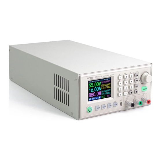
RD6006, RD6012, RD6018 DC Power Supplies
with Custom Firmware by UniSoft
A big thanks to UniSoft for both writing the firmware and technical assistance in creating this document.
This document is user created and definitely has errors and omissions.
For any correction or additions to this document, contact
Primary Author:
Contributing Authors:
Use with Caution.
or through the
associated forum thread
Sunkmail (Scott Mitten)
Dougg (Doug G.)
bateau020
Sunkmail
by the link provided,
on EEVBlog.com.
Latest Document Change: March 19, 2021
Advertisement
Table of Contents

Subscribe to Our Youtube Channel
Related Manuals for Riden RD60 Series


Summary of Contents for Riden RD60 Series
- Page 1 RD6006, RD6012, RD6018 DC Power Supplies with Custom Firmware by UniSoft Primary Author: Sunkmail (Scott Mitten) Contributing Authors: Dougg (Doug G.) bateau020 A big thanks to UniSoft for both writing the firmware and technical assistance in creating this document. This document is user created and definitely has errors and omissions. Use with Caution.
-
Page 2: Table Of Contents
5. System Isolation 6. How to Install Custom Firmware 6.1. Prepare the RD60xx 6.2. If you use UniSoft's RDFlasher on Windows 6.3. If you use Timo Kokkonen's Riden flashtool 7. Front Panel Layout 7.1. Display Screen Layout 8. System Settings Navigation 9. - Page 3 21.4. Charging Strategies 21.4.1. Time limit 21.4.2. Capacity limit 21.4.3. Current limit 21.4.4. Temperature limit 21.4.5. dV/dT 21.4.6. Float Charging (aka Trickle Charging) 22. Reference Information: 22.1. Original Riden Manual 22.2. Fuses 22.3. Short Circuit Response Time Testing 22.4. Miscellaneous...
-
Page 4: Introduction
The RD60xx_s are manufactured by the Hangzhou Ruideng Technology Co. Ltd. of Zhejiang, China. Hereafter the manufacturer will be referred to as Ruideng or Riden; the latter is the name that appears on the front of these power supplies. -
Page 5: Document Status
2. Document Status This document was started in February 2021. The most recent beta firmwares at the time of this document is version RD6006 - zip file: RD60061_V1.34.1n.zip RD6012 - zip file: RD60121_V1.33.1n.zip RD6018 - zip file: RD60181_V1.34.1n.zip All released on 19 March 2021. Each firmware will also work on the corresponding “W”... -
Page 6: Nomenclature & Formatting
4. Nomenclature & Formatting ● Items in double quotes (“ ”) refer to Physical buttons. ○ The Font will also be changed to the one used on this line. ● Items in single quotes (‘ ‘) refer to unit settings or modes. ●... -
Page 7: How To Install Custom Firmware
Windows 10 computer. Any OS (MacOS, Linux, Windows): Timo Kokkonen's Riden flashtool. Requires command line and Python 3. 6.1. Prepare the RD60xx IF using the default RD60xx (Riden) Firmware: SHIFT MENU 1. Press “ ”+” ” to enter the menu system. -
Page 8: If You Use Unisoft's Rdflasher On Windows 8
1) Ensure ‘Interface-USB’ is set to the desired baud rate. (115200 is default for Flasher utility.) In all cases: 2) Confirm the device ‘Address’. 3) Turn OFF the Primary Power Supply. 4) Ensure you have a USB cable connected from your computer to the micro-USB port on the front of the RD60xx. - Page 9 2) In the RDFlasher utility: a) Ensure your Port, Baudrate and Device Address are set for your RD60xx. b) Select the desired firmware from the “Firmware File” dropdown box. < Turn ON the RD60xx’s Primary Power Supply > c) Click the ‘Connect’ button. d) Click the ‘Write’...
-
Page 10: If You Use Timo Kokkonen's Riden Flashtool
6.3. If you use Timo Kokkonen's Riden flashtool This tool can be used on many devices and OSes that have support for python3: Windows, Mac, Linux. It also works on devices like the raspberry Pi. It requires use of the command line. Be sure you are familiar with that. -
Page 11: Front Panel Layout
7. Front Panel Layout POWER “ ” button Output Positive (+) Binding post / terminal General Purpose (+) Output SHIFT “ ” button ON/OFF Output “ ” button “ ” button ENCODER “ ” knob I-SET “ ” button Direction arrows V-SET “... -
Page 12: Display Screen Layout
7.1. Display Screen Layout {ToDo: Add info for the areas of the display} {ie, Status area, The Caption area, Normal operating Icon, Memory location Icon, etc} {Include Icons that may show up, eg internal Fan, LOCK, buzzer, Etc.} 8. System Settings Navigation To Enter Global Settings: To Change Selection Value: ◄... -
Page 13: Global Menu Pages
9. Global Menu Pages 9.1. ‘Battery’ Icon Page 9.1.1. Battery Charger Group CutOff current CutOff temp. CutOff time CutOff cap. CutOff -dV/dT Reset metrics Charge Buzzer 9.2. ‘Gear’ Icon Page 9.2.1. Power Group Update Rate Boot Logo Power State Boot Output 9.2.3. -
Page 14: Home' Icon Page
9.3. ‘Home’ Icon Page 9.3.1. Interface Group -- Show OCP -- Show OPP Language -- Show RL Layout ° -- Show t -EXT -- Show V-BATT 9.3.2. Appearance Group -- Show t° -BATT Digits Style -- Show TIME Leading Zeros -- Show CHARGE Status Info Mem Hint... -
Page 15: Disc' Icon - Memory Location Values Menu
9.4. ‘Disc’ Icon - Memory Location Values Menu {Add description of how this menu works here} {placeholder} {placeholder} {placeholder} {placeholder} {placeholder} {placeholder} {placeholder} {placeholder} {placeholder} {placeholder} 9.5. ‘Screwdriver’ Icon Page Under Construction This menu is currently not in use 9.6. ‘Info’ Icon - Device Information Page (Read Only) Product Model Serial Number... -
Page 16: Quick Settings" (Qs) Menu Layout
11. “Quick Settings” (QS) Menu Layout ▼ SHIFT “ ” + “ ” ORP set ORP delay Graph Window 12. Other Settings Can Only be Enabled by Panel buttons I-SET Press “ ” I-SET SHIFT Press “ ” + “ ”... -
Page 17: Button Actions & Shortcuts
13. Button Actions & ShortCuts Activate Screensaver ● “ ” Current Session’ Menu ‘ ▲ SHIFT “ ” + “ ” 13.1. Graph Mode Only: Display Layout Enter View Mode ◄ ► “ ” or “ ” ENTER “ ” + “ ”... -
Page 18: Description Of Each Setting's Options
14. Description of Each Setting’s Options Address ➥ Communication 001 - 255 Settable Range: Used to uniquely identify unit when multiple devices connected AutoPowerOff ➥ Power Settings Never / 00h01m - 59h59m Settable Range: Automatically Power off after specified time IF RD60xx unit is in idle mode. Idle mode = output off, no user interaction, no communication. - Page 19 Boot Output ➥ Power Settings ON/OFF Disable Output will remain OFF until the “ ” button is pushed. Enable Turn on the output automatically upon Boot-up. LastState Return to the ON/OFF state from the last RD600x shut-off. Power This option is for the RD60xx’s output when the “ ”...
- Page 20 CutOff -dV/dT ➥ Battery Charger NOT monitoring for voltage drop during charging. Value Set in 0.01V steps. IF Set, ● If, 5 minutes after the output is turned on, the voltage drops by more than the specified value, the output will be disabled with the "-dV/dT" status. ●...
- Page 21 CutOff temp. ➥ Battery Charger NOT monitoring external probe for Over Temperature while battery charging. Value Set in 1°steps IF Set AND the temperature reaches, or exceeds, the set value: ● The output will immediately turn OFF. ON/OFF ● The “ ”...
- Page 22 Custom Colours ➥ Colours Custom Colours are used, where set in the ‘Colours Group’ menu options. Default Colours are used. For information on how to set up the Custom Colours see: ‘Colours Group’ Detailed Explanation. CV—>CC Beep ➥ Buzzer Buzzer sounds once when switching from CV to CC mode. Buzzer does NOT sound when switching between modes.
- Page 23 Digits Style ➥ Appearance Change the appearance of digits on screen. Four options are available: 32 64 24 48 Digits Style: Digits Style: 7-Seg v1 7-Seg v2 Digits Style: Digits Style:...
- Page 24 External LED ➥ Power Settings External LED Modification is installed … External LED not used. Red in case of OxP (Protection). Red in CC mode. CC + OxP CV - Green, CC - Yellow, OxP (Protection) - Red. CV-G/CC-R CV - Green; CC - Red. CV-R/CC-G CV - Red;...
- Page 25 I-SET (Set Current, in Amps) I-SET “ ” Can Only be Enabled by Panel button Value of the Current Setpoint, in Amps, for when the unit is in Mode. Encoder Rotate “ ” knob to desired value. ◄ ► Use “ ”...
- Page 26 IF the inrush lasts less than the Delay time and then falls below the value, the unit will continue to operate like a normal CV Mode only Power Supply. However, IF the current draw climbs back above the OCP value: ●...
- Page 27 Press Lock button combination again to disable. Language ➥ Interface Selectable Options: English Chinese Deutsch Français сский Layout ➥ Interface Sets Default screen on Power-up LastState Layout used last on previous session Default Layout - from original, manufacturer Firmware. Customisable Layout, as selected on the ‘Layout 1’...
- Page 28 Leading Zeros ➥ Appearance Change the appearance & behaviour of digits and decimal points on screen. Three options are available: Default: Blank: FloatPoint:...
- Page 29 Max Power ➥ Power Settings Settable Range: Up to Maximum Power Rating of the unit. RD6006: 360W RD6012: 720W RD6018: 1080W Limits output power to set value. - Protects the primary power supply if not capable of providing full power of RD60xx. Manufacturer recommended setting: No higher than 95% of the rated power for the Primary Power...
- Page 30 (Over Current Protection) SHIFT I-SET “ ” + “ ”) Can only be enabled by Panel buttons IF the Output Current exceeds, the set value: ● Unit will enter Protection Mode. ● The output will immediately turn OFF, (See Notes: **) upon entering Protection Mode ○...
- Page 31 ‘MAX Power’ setting. The PC Software and Smartphone App from Ruideng DO NOT recognize this error. IF the RD60xx enters Protection mode due to OPP: Connected (Riden) Software, using any interface (USB, UART), will report Error. (Over Resistance Protection) ➥...
- Page 32 Notes: The PC Software and Smartphone App from Ruideng DO NOT recognize this Error. IF the RD60xx enters Protection mode due to ORP: Connected (Riden) Software, using any interface (USB, UART), will report Error. An example of ORP being tripped.
- Page 33 ● The electronic load was turned on before the RD6018 output was turned ON. ● Graphing was started about 15 seconds before the RD6018 output was turned ON. This graph shows: ● RD6018 output was 9 Volts and 9 Amps, in mode, for approximately 10 seconds.
- Page 34 ○ or react per the setting of ‘External LED’. ● The Normal Operating Mode Indicator is replaced by a red background white ‘OTP’ Icon. Notes: Disabled by setting to 0. Should be set to a higher value than the ambient temperature for proper operation. This setting does NOT affect the RD60xx cooling fan.
- Page 35 ➥ Buzzer Buzzer sounds once when the unit goes into Protection Mode. Buzzer does NOT sound when going into Protection Mode. Power State ➥ Power Settings This option is for the state of the RD60xx itself - NOT the RD60xx’s Output state Power On Turn ON RD60xx unit when the Primary Power Supply...
- Page 36 Save Mult. ➥ Appearance Save the multiplier position for future value adjustments. Multiplier position will return to the lowest position for every change. Multiplier Position refers to the digit highlighted when changing a setting value. {ToDo: Add example image} Note: Upon each power-up of the RD60xx the multiplier will be reset to the lowest position regardless of this setting.
- Page 37 ScrsaverActive ➥ Display Screensaver can activate when RD60xx Output is ON. Screensaver will NOT activate with the RD60xx Output enabled. ScrsaverBright ➥ Display Brightness of display when ‘Screensaver’ activated. Turn off the display (Black Screen) when screensaver is activated. 0 - 4 Settable Range: Notes: ●...
- Page 38 ShiftMemTable ➥ Appearance SHIFT Pressing “ ” button will bring up the complete Memory Table SHIFT Pressing “ ” button will NOT show the memory table SHIFT In either setting, Pressing “ ” will illuminate the button and the unit will await the next button press in the desired button combo.
- Page 39 Skip keys lock ➥ Communication Prevents LOCKing of the physical buttons while the RD60xx unit is communicating. LOCKs the physical controls when communicating. IF OFF, When the RD60xx is communicating via any interface (Interface-UART or Interface-USB), the unit’s controls are LOCKed and can only be controlled by the remote device.
- Page 40 Status Info ➥ Appearance Default Cycles through Ah, Wh, and Sys Temp. (see below) Empty Do NOT show any Status data. Amp Hours accumulated - From Battery Charging Mode. Watt Hours accumulated - From Battery Charging Mode. V-BATT Battery Voltage - Only displayed if a battery is connected. T-BATT External Temperature Value - Only displayed if a battery is connected.
- Page 41 Temperature ➥ Units °C / °F Selectable Options: Changes units for both Internal and External Temperature readings. Time ➥ Date and Time Encoder Rotate the “ ” Knob to the desired value ◄ ► Use “ ” or “ ” to switch selected fields. *** If wrong time is set, it may cause incorrect totals for accumulated values.
- Page 42 Timer Mode {CS Menu} Output Timer is NOT enabled. Single Output ON/OFF will go through ‘Timer Off’ and ‘Timer On’ once. Cyclic Output ON/OFF continuously cycles through ‘Timer Off’ and ‘Timer On’, Off’ is set to 00 00 00, Timer Mode will not do anything. ‘Timer IF set to Single, will need to be re-enable after each use.
- Page 43 Timer Reset {CS Menu} IF changing timer values while the output is already ON. ‘Timer Mode’ timers will reset/begin after exiting from the menu. ‘Timer Mode’ timers will begin when the output is next turned ON. Notes: Timer begins counting after enabling the RD60xx output. (If the output was already enabled, the timer is already running.
- Page 44 RD60xx series. RS485 Interface Mode has NOT Been Tested (UniSoft kept the original Riden firmware code) ● TTL option can be used for any user-defined connection using a Simple UART (No hardware flow control) configuration with 3.3V logic levels.
- Page 45 Protection is not enabled until the Voltage has stopped rising for at least 500ms. The PC Software and Smartphone App from Ruideng DO NOT Recognize this error. IF the RD60xx enters Protection mode due to UVP: Connected (Riden) Software, using any interface (USB, UART), will report an ‘OVP’ Error.
-
Page 46: Colours Group' Detailed Explanation
15. ‘Colours Group’ Detailed Explanation Most display items’ can be changed to a custom colour to fit your individual preferences. The ‘Custom Colours’ menu item is a global On/Off switch for whether the customised colours are used, where customised, or if the entire system uses the default colour scheme. Each item in the ‘Colours Group’... - Page 47 As an alternative, while in mode, it is possible to set the font colour and the background colour, as shown in the examples below.
-
Page 48: Graph Display - Detailed Explanation
16. Graph Display - Detailed Explanation (Note: Riden Calls this ‘Curve mode’ in their documentation) ◄ ► Graph Mode, also known as ‘Layout 3’, is entered by pressing the “ ” or “ ” button until the proper layout is selected. - Page 49 The pause symbol (two, parallel white bars with a blue background) indicates the graph is paused. When running the graph state is shown as a white arrowhead with a red background at the same position. ENTER The pause/run state can be toggled by pressing “ ”...
- Page 50 This example image shows a graph of trickle charging a 12 Volt lead-acid car battery. Battery Charger Group’s setting ‘Cutoff Time’ was set to 1 hour and the external temperature sensor was placed under the RD60xx enclosure. After 1 hour, the charging ceased with 6.64 Watt-hours of energy being transferred.
-
Page 51: Graph (View) Mode
16.1. Graph (View) Mode ENTER “ ” + “ ” In Graph (View) Mode, a vertical red Indexing line appears on the graph (it starts at the right margin) and can be moved left ENCODER and right with the “ ”... -
Page 52: Raw Adc Values And Calibration
17. Raw ADC Values and Calibration The raw ADC values, selectable from the ‘Status info’ setting, can be used to adjust, or confirm, the calibration settings of the RD60xx. Vout = ADC(V) * backVoltageScale / 100000 - backVoltageZero Iout = ADC(I) * backCurrentScale / 100000 - backCurrentZero For example, let's calibrate the "backVoltage"... -
Page 53: How To Adjust The Calibration
17.1. How to Adjust the Calibration From Riden Power Supply Software, Calibration tab, password 168168. To restore factory calibration (it is unique for each device): Pressing " " while Powering ON. {ToDo - Add more detail here, add screen shots … }{A}... -
Page 54: Hardware Modifications
18. Hardware Modifications 18.1. Accessing the Internals {ToDo: Explain how to get at the insides - remove binding posts) -
Page 55: External Led - Modification
18.2. External LED - Modification ON/OFF This modification adds a red LED under the “ ” Button. In combination with the existing green LED, 3 colours become possible, allowing the button to respond in a variety of ways using the ‘External LED’... - Page 56 Mask off around the area of work. Not required, but helps prevent accidental damage to the surrounding area. Drill hole at the location shown. Use the smallest practical drill size to create a hole hook-up wire can pass through. (0.4mm or next smallest available suggested) Try to position the hole near the bottom of the copper area.
- Page 57 Cut the track and prepare pads. Cut as shown in the image above. Scrape off some of the solder mask to expose bare copper. Use a continuity checker to confirm the new island of copper is not shorted to ground. Tin both pads in preparation soldering.
- Page 58 Connect hook-up wire from back side of PCB. Connect wire to the LED through the newly drilled hole. Ensure the wire is fully insulated from the ground plane on the back of the PCB. (The wire’s insulation should be passing through the hole.) Connect the other end of the hook-up wire to the pad shown, through the 470 Ω...
- Page 59 9) Test / Reassemble Unit. Here is the result… As an alternative solution... Illuminate the button from the side by installing a Bright LED inside the case. For example:...
-
Page 60: Front Power Switch - Modification
18.3. Front Power Switch - Modification {To Do: Insert instructions for adding a front power switch} {Reference from Change logs: + Added option "Power Switch" to turn On/Off the primary PSU. (5V standby power supply required). (Note: Adds a 3 second power-on delay). The control output is routed to the PA14 port (pin 4 of the J2 connector). -
Page 61: Improve Internal Thermal Measurement Accuracy
18.4. Improve Internal Thermal Measurement Accuracy Apply thermal paste between the thermistor and heatsink to more accurately display the temperature. 18.5. Using the TTL Interface User example from EEVBlog forum. Communication Protocol: From EEVBlog post: Protocol reverse engineering HERE. -
Page 62: Output Surge Problem - Hardware Bug, With Fix
18.6. Output Surge Problem - Hardware Bug, With Fix Some RD60xx have a small hardware problem… Depending on your version and your primary supply, there may be a surge at the output when the primary power supply is turned on. This occurs regardless of the ‘Boot Output’... - Page 63 Schematic view of the part to replace Exact location of R22 on the PCB inside the RD60xx. (With 56K Resistor installed.)
- Page 64 Original components are small 0603 footprints, but the larger 0805 footprint can be used as a replacement with minimal effort. (Need to scrape off a little solder mask) 0805 Components can (fairly) easily fit for mod - (75K Resistor Installed) The output surge becomes much smaller.
-
Page 65: How To Connect With Wifi
IP connections from other devices. The RD60xx expects the "server" to be listening on port 8080. It is possible to modify the WiFi module’s behaviour though, as it is built around a very common device (the ESP12-F). See https://cuttlefishblacknet.wordpress.com/2020/03/01/riden-rd6006-wifi/ https://community.home-assistant.io/t/riden-rd6006-dc-power-supply-ha-support-wifi/163849 and the ESP User Guide. -
Page 66: If Wifi Has Been Configured Previously
What happens during this step? ○ The RD60xx and the mobile app use the ESPTOUCH protocol. The RD60xx starts listening to the network (in promiscuous mode) for information that the mobile app sends out over the network. Once the RD60xx has read that information, it will show the IP address read on screen. -
Page 67: Other Software And Utilities
20. Other Software and Utilities 20.1. ScreenDumper Utility UniSoft’s ‘Screen Dumper’ for Windows, Latest Version The ScreenDumper utility is connected to your computer in the same way as the RDFlasher utility. Once connected, you can capture the RD60xx’s Display and save it as an image file. (Note: This image is from a pre-release of RDScreenDumper v1.3 - v1.2 is the latest released version) CAUTION!!!! This utility requires approximately 14 seconds to receive a screen capture from the RD60xx unit... -
Page 68: How To Change The Boot Logo Image
20.2. How to Change the Boot Logo Image TODO: Re-Write instructions from original (bad english Riden manual) for changing Boot Logo Image}... -
Page 69: Battery Charging Methods With The Rd60Xx
21. Battery Charging Methods with the RD60xx This power supply can be used to charge a wide variety of different battery types and chemistries, and does so by proposing a large variety of charging strategies. This chapter is meant to group them together and to find the right settings for your needs. -
Page 70: Connecting A Battery
You will also need to know the capacity of the battery, which is expressed in Ah or mAh. Often, the charge current is chosen depending on the capacity. In that case, recommendations for charge current are likely expressed in “C”, or “Charge rate” or A/Ah. If a battery has a capacity of 2Ah, its C is 2A. If a charge current is expressed as 0.1C, it would be 0.2A for a 2Ah battery, and 70mA for a 700mAh battery. -
Page 71: Battery Settings
21.3. Battery settings SHIFT MENU When the battery is detected, entering the menu as usual (via “ ”+” ”), will bring you directly to the menu for various battery charging settings. That menu is also identifiable by the battery symbol being highlighted, with a red background, in the bottom left of the screen: See chapter 14. -
Page 72: Current Limit
Every type of battery has its own recommendations on how to set the charge current with this method, but in general, charging an empty battery at 0.1C up to 100% of the rated capacity can be relatively safe. Like with the time limit, the capacity limit you set must be adapted to the initial charge state of the battery, as the charger cannot know the pre-existing charge. -
Page 73: Dv/Dt
● Inhibit charging or adapt the charge current when the temperature is too low, as might be useful for Lithium-ion batteries. If you want to improve this, you can always hook the RD60xx up to a computer, and act on the temperature from there. -
Page 74: Float Charging (Aka Trickle Charging)
On the above curve you can see the red voltage line has a small drop at the end, it is the -dv/dt and signals the battery is full. The RD60xx with the “n” firmware has experimental support for this, via CutOff -dV/dT, Due to the low resolution of the ADC, it is best to combine this with... -
Page 75: Reference Information
22. Reference Information: 22.1. Original Riden Manual https://drive.google.com/drive/folders/1V0l6P1sIJilN1yBOsTO9YGLVdkuO0cX9 22.2. Fuses 1808 SMD Fuses, RD6006 - 10A RD6012 - 20A RD6018 - 25A Note: Image for reference only. Value shown is NOT correct for the RD60xx. Example datasheet... -
Page 76: Short Circuit Response Time Testing
22.3. Short Circuit Response Time Testing Test 1: Setup: 5 Ohm (Two 10 W, 10 Ω resistors in parallel) Unit: RD6018 Load: V-SET: I-SET: Test method: Output was turned ON and allowed to settle at 10V, 2A. A short circuit was introduced. Results: Starting from 2 Amps, the current goes up to ~ 27 Amps (perhaps higher) for about 200 microseconds then settles back to around 10 Amps after about 600 microseconds. -
Page 77: Miscellaneous
Test 2: The same test was repeated using a Fluke 80i-110s AC/DC Current Probe in ‘High Current’ mode. Results: The power at the first voltage and current intercept was around 500 Watts. The current peaked at over 100 Amps. (Happily, it is only for about 50 microseconds.) 22.4.
Need help?
Do you have a question about the RD60 Series and is the answer not in the manual?
Questions and answers