
Related Manuals for JUKI Jtron JTR-KM3680N/WSU Series


Summary of Contents for JUKI Jtron JTR-KM3680N/WSU Series
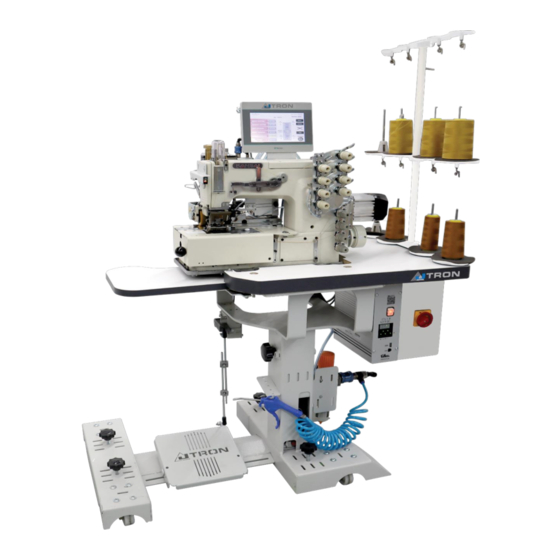
- Page 1 Waistband Sewing Unit (Double Chainstitch) JTR-KM3680N/WSU Series INSTRUCTION MANUAL No.JTR000 KM3680NWSU-TM...
-
Page 2: Table Of Contents
CONTENTS CONFIGURATION OF THE MACHINE SPECIFICATION INSTALLATION PREPERATION FOR OPERATION PANEL ADJUSTMENT LIST OF PATTERN DATA 8) CAUSES AND COUNTERMEASURES... -
Page 3: Configuration Of The Machine
CONFIGURATION OF THE MACHINE ❶ ❽ MACHINE HEAD MOTOR GROUP ❷ ❾ PANEL SEWING AND FOOT GROUP ❸ ❿ MAIN SWITCH PULLER GROUP ❹ ⓫ CONTROL BOX UPPER PULLER GROUP ❺ ⓬ CHASSIS AIR BLOWING GROUP ❻ ⓭ PEDAL SET THREAD STAND ❼... -
Page 4: Specification
SPECIFICATION Category Description MACHINE HEAD K/S DLR-1509P MODEL NAME JTR-KM3680N-WSU MAIN MOTOR EFKA SERVO MOTOR DC 1550 MAIN MOTOR DRIVE EFKA AB321A MAXIMUM SEWING SPEED 3200sti/min DELIVERY SPEED : 2800sti/min STITCH LENGTH Min : 1,5mm Max: 3,5mm NEEDLE TYPE GB TV-5 #21 x 4 needles GAUGE JTRON GAUGE(1/2 - 3/8 - 1/4 - 1/8) WAISTBAND CUTTER WITDH... -
Page 5: Installation
INSTALLATION 3.1) The machine is delivered as below There are 10 pieces of screws to stabilize the machine to the wooden box. When the stated screws removed machine is ready to use such as in the photo. - Page 6 3.2) Thread stand assembly Insert thread stand and rubber into the table. Tighten lock nut so that the thread stand will not be able to move. 3.3) Connecting the power supply The machine is not supplied with a power plug. It is therefore necessarry for you to select to plug that maches the receptacle availabe under a given operating environment and attach it to the power cable.
- Page 7 3.4) The supply air to the machine The air hose is shipped ready to use.
- Page 8 3.5) How to adjust the table height? 3.5.1) Remove the hexagon-head bolt (2 pieces). 3.5.2) Prepare the bottle jack arm.
- Page 9 3.5.3) Remove handle bolt. If the handle bolt does not turn, reduce the load by moving the arm up and down(1) or counterclockwise(2). Loosening the hand bolt may cause the table to be lowered sharply. 3.5.4) Put the arm into knob (3) and turn clockwise until they no longer turn. If the bolts are tight, it cannot be lifted.
- Page 10 3.5.6) Adjust the table height Adjust the table height by moving the arm up and down or counterclockwise. The table height can be changed at certain distances. Therefore, adjust according to the hole marked in red. 3.5.7) Install handle bolt. 3.5.8) Install the hexagon-head bolt (2 pieces).
- Page 11 4) PREPARATION FOR OPERATION 4.1) Please put the Kansai genuine oil from upper cover of the machine head. (Please refer to machine head instructions KS-DLR1509P) a) Remove oil viewer A and supply oil until oil is being filled up to the line B of oil gauge C. The oil level should be checked and kept between line B and D while machine is in use.
- Page 12 4.2) Threading the machine. (Please refer to machine head instructions – KS-DLR1509P) 4.3) Switch on the machine. 4.4) How to install waistband to stand and feed the waistband attachment? 4.4.1) Put waistband to its stand as in the picture.
- Page 13 4.4.2) Feed the waistband to its attachment with the given steps. 4.4.2.1) The edges of the waistband should be cut on front edges to insert the band to attachment easier.(see picture below) 4.4.2.2) After feeding the waistband to all the way of the attachments first canal, turn the waist band and insert the second canal.
-
Page 14: Panel
PANEL 5.1) Main Page Description Test: I/O Check Page [Ref : 5.2)] Manual mode button Automatic mode button Needle count of left needle stitch skipping at the beginning Needle count of right needle stitch skipping at the beginning Cloth cutting at the beginning Left stitch skipping at the end Cloth cutting at the end Right stitch skipping at the end... - Page 15 5.2) I/O Check Page(Test page) Needle counting control Unseam control Knife sensor control Machine revolution Output 5.3) Settings Page 1) The setting of the low speed time at the beginning of the cutting of waistband (Pulse input) 2) The setting of the low speed time at the end of the cutting of waistband (Pulse input) 3) Knife movement time at the beginning (ms) 4) Knife movement time at the end (ms) 5) The stich count until the air cylinder of the rear roller becomes active after front fabric sensor is activated.
-
Page 16: Adjustment
6) ADJUSTMENT 6.1) Knife replacement Note! Cut the air compresser of the machine at first! 6.1.1) Remove air tubes from air clinder Unplug the tubes from the stated sockets. 6.1.2) Eject the knife unit from machine Loosen the “A” screws (2pieces) to eject the knife unit. - Page 17 6.1.3) Detach the fixed knife from the “B” screws(2 pieces) 6.1.4) Detach the moving knife from the “C” screws(3 pices) 6.1.5) Adjust knife tightness Make the adjustment the distance between the moving and the fixed knife with the stated screw Note! It is necessary to loosen “B”...
- Page 18 6.1.6) Placing the new fixed knife After placing the new fixed knife tighten the “B” screws(2 pieces) 6.1.7) Placing the moving knife After placing the new fixed knife tighten the “C” screws(3 pieces) Tighten the “A” screws (2 pieces) to attach the unit in the correct position, the sharp edge of the fixed knife should be aligned parallel with the puller.
- Page 19 6.2) Roller replacement 6.2.1) Lower puller replacement 6.2.1.1) Detach the cover from the stated screws (2 pieces) 6.2.1.1) Remove assembly plate wit the "A" screws(4 pieces) 6.2.1.1) Remove the the plate by removing the imbus screw(1 piece)
- Page 20 6.2.1) Upper puller replacement 6.2.2.1) Loosen the imbus screw (2 pieces) and remove retaining ring(E-Type). 6.2.2.2) Remove the washer and detach the black plate from other plate.
- Page 21 6.2.2.3) Remove upper puller roller 6.2.2.4) Install upper puller roller Then complete the assembly(as in the picture) by reversing the previous steps.
- Page 22 6.3) Air tubes 6.3.1) Rear roller presser adjustment is done via speed controller “1”. Note: Adjustment should be done when air cylinder is at down position. 6.3.2) Unseam air amount is adjusted via speed controller “2”. The adjustment should be adjusted as strong as it provides unseeam and but at the same time the adjusstment should be weak enough not to tangle the thread to needle.
- Page 23 6.4) Sensor adjustment Reflectors(1-2) should be new and should be reflecting back to the sensors Sensor positions(3-4) should aligned the way they could see the reflectors. The machine should be operated on dark mode(5) And the sensitivity(6) adjustment should at the maximum margin. Note! If there is not a fabric on the reflector only green light is on but If there is fabric on the reflector both green and red light will be on...
- Page 24 The button(7) should be pressed to lower down the rear roller(8). When the rear roller is at the down position(8) The dial bar(9) should be adjusted 0.5 MPa via the knob(10) 6.5) Air valves 1)Tension release & left needles unseam feature 2)Tension release &...
-
Page 25: List Of Pattern Data
7) LIST OF PATTERN DATA(SHIPPING VALUES) 7.1) MAIN PAGE 7.1) SETTINGS PAGE... - Page 26 8) CAUSES AND COUNTERMEASURES Q.1) Sensor does not detect the fabric. A1) Check and change the reflectors. Q.2) Rollers does not work properly after a year! A2) Change the rollers. (refer 6.2 Roller replacement)
- Page 27 8500 NW 17TH STREET, SUITE 100, DORAL, FL 33126-1035, U.S.A. PHONE (1)305-594-0059 HTTP https://juki.com Company Name : JUKI MIDDLE EAST (JUKI SINGAPORE PTE. LTD. UAE BRANCH) OFFICE NO, 2511. BLOCK A JAFZA 1, PO BOX 18031, JEBEL ALI, DUBAI UAE PHONE (971)4-8833228 (971)4-8833230 HTTP http://www.juki.com.sg...
Need help?
Do you have a question about the Jtron JTR-KM3680N/WSU Series and is the answer not in the manual?
Questions and answers