Table of Contents
Advertisement
Quick Links
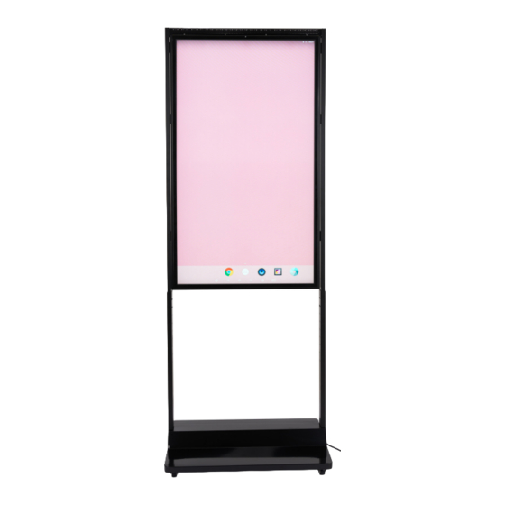
DISPLAYS2GO DIGITAL
55" High Brightness Dual
Sided Digital Window Signage
USER MANUAL
SKUs: DGHBDWS55
Description: 55" High Brightness Dual Sided Digital Window Signage
NOTE: Before using the product, please read the instructions carefully.
Do not attempt to disassemble this product. If the product does not work properly, please call our Customer
Service Department at 1-844-221-3393.
Advertisement
Table of Contents

Related Manuals for Displays2go DGHBDWS55


Summary of Contents for Displays2go DGHBDWS55
- Page 1 55” High Brightness Dual Sided Digital Window Signage USER MANUAL SKUs: DGHBDWS55 Description: 55” High Brightness Dual Sided Digital Window Signage NOTE: Before using the product, please read the instructions carefully. Do not attempt to disassemble this product. If the product does not work properly, please call our Customer...
-
Page 2: Table Of Contents
TABLE OF CONTENTS Safety Warnings and Precautions ......................3 Features ..............................6 Assembly and Connection ........................6 • Important: Assembly Information ..........................6 • Parts List ..................................7 • Interfaces .................................. 8 • Floor Standing Assembly ............................8 • Ceiling Mounted Assembly ............................1 1 Remote Control ............................ -
Page 3: Safety Warnings And Precautions
“Ceiling Mount Assembly”. SAFETY WARNINGS AND PRECAUTIONS Thank you for buying this product from Displays2go. We have taken personal safety into account in product design and carried out rigorous tests in the factory. However, improper installation and use can lead to electric shock and fire. To ensure safe use, maximize the performance of the product, and prolong the service life of the product, please read and follow all instructions carefully before using the product. - Page 4 WARNINGS • Do not use power supplies with DC or AC output other than 12V 3A or mobile power supplies. • Disconnect the power supply before connecting or disconnecting any cable. • Do not place the device in an unstable position to avoid damage or fire. •...
- Page 5 This Manual is for reference only and is subject to change without prior notice. If you have any questions regarding our products, please visit us at www.displays2go.com or contact Displays2go customer service at 844-221-3393 . Scan QR code to visit product page.
-
Page 6: Features
FEATURES 1. Embedded with Android 7.1 smart operating system and unique UI design, bringing you a more convenient operation and better visual experience. 2. Support USB mouse and keyboard, realizing easy manipulation like a computer. Using a mouse for set up is recommended. 3. -
Page 7: Parts List
Failing to ensure proper ventilation the product may result in malfunction or overheating, which may result in a fire. If you have any questions regarding our products, please visit us at www.displays2go.com or contact Displays2go customer service at 844-221-3393. PARTS LIST... -
Page 8: Interfaces
INTERFACES USB 2.0 Power Switch USB 2.0 FLOOR STANDING ASSEMBLY 1. Utilizing the “Floor Stand Siderail Assembly Parts”; assemble two telescopic upper siderails to the lower siderail sections (Fig. 1) with “m4x6 screws” - qty. 4 per side. 2. Attach the two side rail assemblies to the “55” Dual Sided Screen” (Fig. 2 & 3) with “m4x6 screws”... - Page 9 3. Pull out the internal and external power cords & LAN cable each side in advance and lead them to the bottom of the base along the inside of the telescopic siderails (Fig. 4). Then fix the telescopic siderails to the “Floor Stand Base” with “m6x35 screws” - qty. 4 per side. Note: Use the pre-attached 3-way spring lever connector block when connecting the internal power cord sections (see inset below).
- Page 10 4. Attach the “Siderail Cover Plates” with “m3x5 screws” - qty. 4 per cover plate (Fig. 6). Fig. 6 5. Fully assembled floor standing 55” High Brightness Dual Sided Digital Window Signage (Fig. 7). Fig. 7 PAGE 10...
-
Page 11: Ceiling Mounted Assembly
CEILING MOUNT ASSEMBLY NOTE: Professional installation is recommended when choosing to install the digi- tal signage by the “Ceiling Mount Assembly”. 1. Utilizing the “Ceiling Mount Siderail Assembly Parts”; assemble two telescopic upper siderails to the lower siderail sections (Fig. 1) with “m4x6 screws” - qty. 4 per side. 2. - Page 12 3. Pull out the internal and external power cords & LAN cable each side in advance and lead them to the bottom of the base along the inside of the telescopic siderails (Fig. 4). Note: Use the pre-attached 3-way spring lever connector block when connecting the internal power cord sections (see inset below).
- Page 13 5. Utilizing the “Ceiling Mount Hanger Assembly Parts”; attach the hanger to the ceiling with the supplied “m10x75 Hex Nut Sleeve Anchors” - qty. 3 (Fig. 6). Note: The “m10x75 Hex Nut Sleeve Anchors” are for use in masonry. Consult your contractor or local hardware store when mounting into drywall or securing to support joists (drop panel ceilings).
- Page 14 7. Turn on the external power supply of the displays screen and attach the hanger cover with “m4x6 screws” - qty. 4 (Fig. 8). Note: Signage can be plugged in or hardwired; consult an electrician for unit to be hardwired. Fig.
-
Page 15: Remote Control
REMOTE CONTROL Installing Batteries for the Remote Control • Aim the remote control at the receiver window. Do not place any object between the remote control and the receiver window to avoid interference with the normal operation. • Keep the remote control away from violent vibration. In addition, do not set or place the remote control in direct sunlight, or else the remote control may be deformed by heat. -
Page 16: Description Of Basic Operation
BASIC OPERATION OF SYSTEM Power On/Standby • Insert the power plug into outlet. If the equipment has a power switch button, switching to “|” will turn it on. Pressing, “O,” will put the equipment in standby state. • When powered on, enter “System Assistant,” and press the “ ” button on the remote control, and the equipment enters standby state. -
Page 17: File Manager
File Management 1. Click the Main Apps button on the home page to enter the Apps menu interface (Fig. 1). 2. Click the “Explorer” icon (Fig. 2) and enter Explorer menu (Fig. 3). 3. Click desired device in the Explorer menu to read the files from each. Fig.1 Fig.2 Fig.3... -
Page 18: Description Of Settings Interface
Fig.4 Fig.5 Fig.6 Description of Settings Interface ICON DESCRIPTION ICON DESCRIPTION WiFi Switch Memory Bluetooth Users Data Usage Location Display Security Notifications Accounts Sound Google Apps Languages & Input Screenshot Settings Backup & Reset Storage Date & Time Battery NOTE: Click the icon in the menu to hide the Home Button. -
Page 19: Diviex App Introduction
DIVIEX APP INTRODUCTION How to Upload Media Files 1. Plug in your USB drive to the computer. Open the drive in Windows Explorer (see pg. 1 1) and create a new folder, rename it “MediaFolder”. 2. Open “MediaFolder,” create 3 subfolders, and change their names to “Images,” “Videos,” “Music.” 3. -
Page 20: Edit Picture(S)
Edit Picture This function shows all pictures, all pictures can be edited or removed, as desired. Crop There are four corner handles and four border handles to crop the picture. Click and drag a handle to reshape the image to desired size. Filter A variety of different filters are available in the filter gallery below the image. -
Page 21: Music
Music This function allows you to add music files to play in the background of your display. In order to do this, you must add all desired music files in the playlist library. 1. Add desired background music to “Playing List Music”... -
Page 22: Choose System Language
System Language 1. Navigate into Settings, then click “Language & Input.” 2. Click “Languages,” then click “Add a Language.” 3. You can add the required system language from the existing list of languages. Scroll to find the desired language, then select to add to system. 4. -
Page 23: Technical Specifications
Technical Specifications Item Specification Panel LCD Size 55” Resolution 1980*1080 (pixels) Brightness (typ.)/(min.) 3000 nits outward facing screen / 1000 nits inward faciing screen Contrast (typ.) 1 100”1 (typ.) Response (ms) 10ms (typ.) Pixel Pitch 0.21 (H) mm * 0.63 (V) mm Refresh Rate 60Hz Viewing Angle... -
Page 24: Cleaning And Maintenance
I/O Interfaces Ethernet (RJ45) HDMI I/O Interfaces (cont’d) Headset Structure Net Weight 48kg Gross Weight 65kg Unit Dimensions (WxDxH) 1920~2160*788.3*500mm (Standing) 2330~2650*792.6*74mm (hanging) Package Dimensions (WxDxH) ≈1410*250*910mm (Frame) 800*245*510mm(Base) Shell Material Aluminum profile/sheet metal Shell Color Black Language English/Simplified Chinese Cleaning and Maintenance 1. -
Page 25: Troubleshooting
Troubleshooting Guide Issue Probable Cause Solutions -Check that unit is plugged into wall. -Confirm that the power cord is connected -Unit is not plugged into the wall. to the terminal on the back of the unit. -Power cord not properly -Turn the on/off toggle switch to the “on”... - Page 26 3 dots > play > check desired Loop option. If all of the potential solutions have been tested for a particular issue and problems have not been resolved, contact a customer service representative for guidance. Contact Information: Website: www.displays2go.com Phone: 844-221-3393 PAGE 26...
Need help?
Do you have a question about the DGHBDWS55 and is the answer not in the manual?
Questions and answers