Table of Contents
Troubleshooting

Subscribe to Our Youtube Channel
Related Manuals for Endress+Hauser analytikjena qTOWER3auto Series


Summary of Contents for Endress+Hauser analytikjena qTOWER3auto Series
- Page 1 Service Manual of the Rev. A qTOWER auto series Valid from: 06.05.2021 Service Manual of the qTOWER auto series Revision: 2021-01 Service Manual qTOWER Auto Rev. 01 / valid from: 06.05.2021 Page 1 of 125 Page 1 to 116...
- Page 2 Service Manual of the Rev. A qTOWER auto series Valid from: 06.05.2021 Manufacture Analytik Jena GmbH Konrad-Zuse-Str.1 07745 Jena Germany Phone + 49 3641 77 70 Fax + 49 3641 77 92 79 Email service@analytik-jena.com Production Biometra GmbH Rudolf-Wissell-Str. 30 37079 Göttingen ...
- Page 3 Service Manual of the Rev. A qTOWER auto series Valid from: 06.05.2021 Overview of the revisions Version Date Modification RV-01-2021 06.05.2021 none (new) Service Manual qTOWER Auto Rev. 01 / valid from: 06.05.2021 Page 1 of 125 Page 3 to 116...
-
Page 4: Table Of Contents
Service Manual of the Rev. A qTOWER auto series Valid from: 06.05.2021 Contents General Description of qTOWER auto devices ......7 Intended Use ....................7 Safety instruction ............... 8 Symbols and signal words ................. 8 Safety symbols on the qTOWER³ auto ............9 Technical condition of qTOWER³... - Page 5 Service Manual of the Rev. A qTOWER auto series Valid from: 06.05.2021 Firmware updates ................48 5.1.0 Firmware update of device ............... 48 5.2.0 Documentation of the Firmware-UniversalUpdate QTOWER³ ....48 5.3.0 Update the firmware of the Power unit via RS232 ........49 5.4.0 Update the firmware of the Control unit via RS232 .........
- Page 6 Service Manual of the Rev. A qTOWER auto series Valid from: 06.05.2021 9.1.0 TP Measuring ....................90 9.1.2 Test procedure and description ..............91 9.2.0 Working with single commands using the Thermal tool TUSB....93 Error messages of the software qPCR auto soft ..........96 9.3.1 Error codes ....................
-
Page 7: General Description Of Qtower Auto Devices
Service Manual of the Rev. 01-2021 qTOWER auto Valid from: 06.05.2021 General Description of qTOWER auto devices Intended Use The qTOWER auto and ³84 auto are thermal cyclers for amplifying DNA by way of the poly- merase chain reaction (PCR) licensed for real-time PCR experiments. The integrated detector enables the measurement of the sample fluorescence in up to six spectral channels during the PCR, with the filters used in the color or FRET modules being ex- actly matched to the properties of the most frequently used fluorescence dyes, thereby per-... -
Page 8: Safety Instruction
Service Manual of the Rev. 01-2021 qTOWER auto Valid from: 06.05.2021 Safety instruction Symbols and signal words Service Manual qTOWER Auto Rev. 01 / valid from: 06.05.2021 Page 1 of 125 Page 8 to 116... -
Page 9: Safety Symbols On The Qtower³ Auto
Service Manual of the Rev. 01-2021 qTOWER auto Valid from: 06.05.2021 Safety symbols on the qTOWER³ auto The qTOWER³ auto is fitted with safety symbols, the content of which must always be observed. Dam- aged or missing safety symbols can cause incorrect actions leading to personal injury or material dam- age! The safety symbols must not be removed! Dam-aged safety symbols must be replaced without de- lay! The following safety symbols are attached to the qTOWER³... -
Page 10: Requirements For The Service Personnel
Service Manual of the Rev. 01-2021 qTOWER auto Valid from: 06.05.2021 Requirements for the service personnel The operating and service personnel must have access to the manual at all times! The qTOWER³ auto may only be repaired by qualified personnel who have been instructed in the handling of the unit. -
Page 11: Safety Instructions - Electrical Equipment
Service Manual of the Rev. 01-2021 qTOWER auto Valid from: 06.05.2021 Safety instructions - electrical equipment Work on electrical components of the qTOWER³ auto may only be carried out by a qualified electri- cian in accordance with the applicable electrical engineering rules. Life-threatening electrical volt- ages may occur in the interior of the qTOWER³... -
Page 12: Technical Data
Service Manual of the Rev. 01-2021 qTOWER auto Valid from: 06.05.2021 Technical data qTOWER³ auto and qTOWER³ 84 auto This data can be found in the manual of the device. Service Manual qTOWER Auto Rev. 01 / valid from: 06.05.2021 Page 1 of 125 Page 12 to 116... -
Page 13: Technical Description Of Instrument
Service Manual of the Rev. 01-2021 qTOWER auto Valid from: 06.05.2021 Technical description of instrument qTOWER³ auto - Instrument overview Service Manual qTOWER Auto Rev. 01 / valid from: 06.05.2021 Page 1 of 125 Page 13 to 116... -
Page 14: Basic Module 1 And 2
Service Manual of the Rev. 01-2021 qTOWER auto Valid from: 06.05.2021 Basic Module 1 and 2 4.2.1 Front and rear panel Fig. 2 Front view Fig. 3 Rear view Service Manual qTOWER Auto Rev. 01 / valid from: 06.05.2021 Page 1 of 125 Page 14 to 116... -
Page 15: Basic Housing- Front And Rear Panel
Service Manual of the Rev. 01-2021 qTOWER auto Valid from: 06.05.2021 4.2.2 Basic housing- Front and rear panel To be able to check or repair components in a basic module, the housing must first be dismantled. The qTOWER³ auto front plates are fixed by six Magnetics on the metal housing. To do this, the front panel can be pulled off the housing, That’s why one images of this device are shown here, only. -
Page 16: Basic Housing- Locking Screws
Service Manual of the Rev. 01-2021 qTOWER auto Valid from: 06.05.2021 4.2.3 Basic housing- locking screws To remove the upper housing, remove the two screws located behind the front panel. The housing can be pulled off to the rear after the 2 screws have been removed. Fig. -
Page 17: Basic Housing- Rear Panel Overview
Service Manual of the Rev. 01-2021 qTOWER auto Valid from: 06.05.2021 Fig. 10 shows the Basic unit from the front after the housing has been removed. Fig. 10 Basic lower housing, 10-3107-802-61 Fig. 11 shows the Rear panel with cable Fig. -
Page 18: Basic Housing- Base Mounting
Service Manual of the Rev. 01-2021 qTOWER auto Valid from: 06.05.2021 Fig. 13 Fan, 10-3108-173-96 mounted on the rear panel Fig. 14 USB hub, 10-3108-170-83 mounted on the rear panel 4.2.6 Basic housing- Base mounting Since the fans in the base assembly can become clogged with dust, they must be cleaned from time to time. - Page 19 Service Manual of the Rev. 01-2021 qTOWER auto Valid from: 06.05.2021 Fig. 15 Fig.16 Fig. 17 Service Manual qTOWER Auto Rev. 01 / valid from: 06.05.2021 Page 1 of 125 Page 19 to 116...
- Page 20 Service Manual of the Rev. 01-2021 qTOWER auto Valid from: 06.05.2021 4.2.7 Basic housing- Base boards and plugs Figs. 18 to 21 show the circuit boards in the base assembly, which can be seen after disman- tling the housing. On the right side is the USB board (SPI-RS485-LP board), 10-3108-140-83 see Fig. 19. It is responsible for amplifying and booting the internal USB signal.
-
Page 21: Qtower³ Auto Optical Head
Service Manual of the Rev. 01-2021 qTOWER auto Valid from: 06.05.2021 qTOWER³ auto optical head 4.3.1 qTOWER³ auto 96 well – Optical unit - construction Based on the design of the different rotor types between 96 well and 384 well, the rotor of the 96 well version is installed horizontally. -
Page 22: Qtower³ Auto 96 Well - Optical Unit - Assembled Component
Service Manual of the Rev. 01-2021 qTOWER auto Valid from: 06.05.2021 4.3.2 qTOWER³ auto 96 well – Optical unit – assembled component For the qTOWER³ auto, the schematic representation of the detection head is shown in fig. 23 to 24. It is designed to the 96 well plate and is characterized by a horizontal color module wheel. -
Page 23: Qtower³ Auto 96 Well- Optical Unit - Construction
Service Manual of the Rev. 01-2021 qTOWER auto Valid from: 06.05.2021 4.3.3 qTOWER³ auto 96 well- Optical unit - construction Fig. 24 optical unit construction (96 well format) Service Manual qTOWER Auto Rev. 01 / valid from: 06.05.2021 Page 1 of 125 Page 23 to 116... -
Page 24: Qtower³ 84 Auto - 384 Well Unit - Assembled Component
Service Manual of the Rev. 01-2021 qTOWER auto Valid from: 06.05.2021 4.3.4 qTOWER³ 84 auto - 384 well unit - assembled component Rear view Fig. 25 Front view Fig. 26 Fig. 25 Back side (left figure) of the optical unit (384 well format) Fig. -
Page 25: Scanner And Lift Construction
Service Manual of the Rev. 01-2021 qTOWER auto Valid from: 06.05.2021 Scanner and lift construction The scanner and the lift are mounted on two superimposed frames. The scanner with spindle motor and lin- ear drive is mounted on the lower frame. The lift is mounted on the upper frame. Both frames are fixed to the block with screws. - Page 26 Service Manual of the Rev. 01-2021 qTOWER auto Valid from: 06.05.2021 4.4.1 Scanner unit The scanner's spindle motor and linear drive are mounted on the scanner's lower frame, shown in Fig. Fig. 28 assembled motor and linear drive The components of the lift, consisting of the drive motor and belt guide, are mounted on the upper frame, shown as Figure 29.
- Page 27 Service Manual of the Rev. 01-2021 qTOWER auto Valid from: 06.05.2021 4.4.2 Lift unit The motor of the lifting spindle moves the lifting device (scanner) via a belt. The scanner unit is mounted together with the lifting device. To do this, the scanner frame is attached with four screws (2 screws are attached on both sides).
- Page 28 Service Manual of the Rev. 01-2021 qTOWER auto Valid from: 06.05.2021 4.4.3 Heated lid unit The heated lid; consists of the heating board, the temperature sensor and a temperature fuse. The 96 well heater mat 10-31-00-416-12, is fixed to the heated lid plate with 2 screws. The heater mat for the 384 well unit is, 10-3108-910-83.
-
Page 29: Glass Plate Unit
Service Manual of the Rev. 01-2021 qTOWER auto Valid from: 06.05.2021 4.4.4 Glass plate unit The glass plate 10-3108-011-96; To protect against optical damages and dust, an glass plate is in-stalled in the lid. This glass plate shown is supplied in a protective film. This blue protec- tive film must be carefully removed and the glass plate cleaned before installation. -
Page 30: Real-Time Lp Board Spindel Motor And Coller Plugs
Service Manual of the Rev. 01-2021 qTOWER auto Valid from: 06.05.2021 Plug of Lift Mikro switch Fig. 35 Fig. 36 Heater 10 -20 Ohms blue wires Plug- to the Motor Lift Sensor 10 – 20 Kilo-Ohms black wires 4.4.6 Real-Time LP board Spindel motor and coller plugs The Real-Time LP board, 10-3108-100-85, assembled on the optical unit. - Page 31 Service Manual of the Rev. 01-2021 qTOWER auto Valid from: 06.05.2021 4.4.7 Detector and (RGBW) light source The Hamamatsu detector, PMT-module H10721, 10-3100-140-14, is a photosensor module, containing a metal package PMT and a high-voltage power supply circuit. In front of the pho- tocathode, an IR blocking filter is mounted.
-
Page 32: Ray Division And Flexible Fibers
Service Manual of the Rev. 01-2021 qTOWER auto Valid from: 06.05.2021 Fig. 42 shows the construction drawing of RGBW light source 10-3100-104-14 Heatsink 4 LMS-bracket with fiber port 5 Socket with adjust facility RGBW-LED Light mix bar 4.4.8 Ray division and flexible fibers Construction The Fig. -
Page 33: Ray Division Mounted With Flexible Fibers
Service Manual of the Rev. 01-2021 qTOWER auto Valid from: 06.05.2021 4.4.9 Ray division mounted with flexible fibers Ray division and flexible fibers 96well Position The following figure 45 and 46 shows an example of the position of the individual fibers on the Scanner carrier (Fig. - Page 34 Service Manual of the Rev. 01-2021 qTOWER auto Valid from: 06.05.2021 Ray division and flexible fibers 384 well The following figure 47 and 48 shows an example of the position of the individual fibers on the scanner carrier (Fig. 47) and rotor (Fig.48) of a 384 well block device. The individual positions are named with position A to position I.
-
Page 35: Module 3 - Power Module
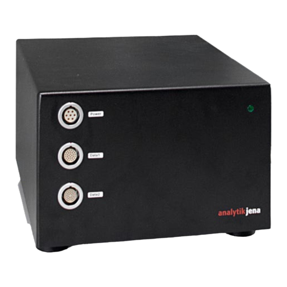
Service Manual of the Rev. 01-2021 qTOWER auto Valid from: 06.05.2021 Module 3 - Power Module The qTOWER3 auto power module 10-3107-531-25 is used to provide the automated real-time PCR qTOWER³ auto thermal cycler with power. The external solution allows for flexibility with regards to installation or integration in automation systems. -
Page 36: Rear View
Service Manual of the Rev. 01-2021 qTOWER auto Valid from: 06.05.2021 4.5.1.2 Rear view On the rear of the qTOWER³ auto, in addition to the service connection and the Ethernet port, there is the mains connection socket, with the integrated fuse compartment and the mains switch. 1 Type plate 2 Warning note 3 Service connection... -
Page 37: The Power Module Housing
Service Manual of the Rev. 01-2021 qTOWER auto Valid from: 06.05.2021 Fig. 52 Inspect condition of fuses. For repair replace all of them. Replace the fuses by similar fuses, (400.221), for example in Europe 10 A 250V. In order to change the operating voltage. Replace the end cap to reach the setting- switch at the bottom of the device. - Page 38 Service Manual of the Rev. 01-2021 qTOWER auto Valid from: 06.05.2021 Fig. 54 Base plate, 10-3107-550-14 of the power modul. The black metal housing, 10-3107-552-14 (left side) and the power module basis unit with the Aluminum base plate, 10-3107-550-14, on the right side, as Fig. 55 Fig.
-
Page 39: Internal Cable Connections Of The Power Modul (Black Housing)
Service Manual of the Rev. 01-2021 qTOWER auto Valid from: 06.05.2021 4.5.1.5 Internal cable connections of the power modul (black housing) Inside the housing, a couple of cable can be find as shown in fig. 56 and 57. - The flat ribbon block sensor cable which is connected to the block sensor (fig 56) - The multicolored HDI Com cable, is for communication over HDI port (fig. -
Page 40: Internal Power Supply And Processor Board
Service Manual of the Rev. 01-2021 qTOWER auto Valid from: 06.05.2021 Fig. 58 connection of the power module 4.5.1.6 Internal power supply and processor board The internal power supply, 10-3107-521-25, as figure 59, is surrounded by further housing. The housing is fixed to the unit with 10 screws, on the Back side, front and on the side, shown as Fig. - Page 41 Service Manual of the Rev. 01-2021 qTOWER auto Valid from: 06.05.2021 Fig. 60 The Processor board, 34-7000-200-86 4.5.1.7 Power board and power control board The power control board (PWR/ CTRL), 10-3108-090-85, is located below the processor board which is fixed with four screws. It is fixed to the metal housing next to the power board with four screws each. It is connected to the RS 232 connection and the Ethernet socket, which are located on the back of the power module Fig.61.
- Page 42 Service Manual of the Rev. 01-2021 qTOWER auto Valid from: 06.05.2021 Next to the power control board (PWR/ CTRL), 10-3108-090-85, (cartially overed by the metal chas- sis) is the power board. It must be removed if you want to replace the board. The plug of the heat lids is located in the middle on the power board.
- Page 43 Service Manual of the Rev. 01-2021 qTOWER auto Valid from: 06.05.2021 4.5.1.9 Power Module - Wiring diagram Wiring diagram of the qTOWER³ auto power module Fig. 65 Service Manual qTOWER Auto Rev. 01 / valid from: 06.05.2021 Page 1 of 125 Page 43 to 116...
-
Page 44: Module 4 - Microtiterplateloader (Mpl)
Service Manual of the Rev. 01-2021 qTOWER auto Valid from: 06.05.2021 Module 4 – MicrotiterPlateLoader (MPL) 4.6.1 MPL overview The qTOWER³ auto is equipped with an motorized, moveable microplate tray for loading the mikro- titerplates. The MPL unit is located between the optical unit and thermal cycler unit (block unit). This component is assembled together with scanner see Fig. -
Page 45: Mpl Drawer On Ground Plate
Service Manual of the Rev. 01-2021 qTOWER auto Valid from: 06.05.2021 4.6.2 MPL drawer on ground plate Module 4 is located below the optics. For repair it is necessary, to remove the unit housing, shown on sheet 15 point 4.2.1. After removing the basic housing, the cover under which the complete optics are located can be seen. -
Page 46: Mpl Drawer Ground Plate
Service Manual of the Rev. 01-2021 qTOWER auto Valid from: 06.05.2021 4.6.5 MPL drawer ground plate Figure 68 shows the assembled drawer with control board. The pre-assembled drawer unit is firmly mounted on the base plate with the MPL board and the drawer motor. The separate MPL board con- trols the microplate drawer drive, see Fig. -
Page 47: Mpl Drawer Wirring Diagram
Service Manual of the Rev. 01-2021 qTOWER auto Valid from: 06.05.2021 4.6.7 MPL drawer wirring diagram Figure 71 shows the wire diagram of MPL drawer unit X 14 QTOWER³ auto drawer wire diagram Figure 71 Service Manual qTOWER Auto Rev. 01 / valid from: 06.05.2021 Page 1 of 125 Page 47 to 116... -
Page 48: Firmware Updates
Service Manual of the Rev. 01-2021 qTOWER auto Valid from: 06.05.2021 Firmware updates 5.1.0 Firmware update of device Note: The firmware update tool is included in the installation routine, but you can also use the external firmware updater. 5.2.0 Documentation of the Firmware-UniversalUpdate QTOWER³ 1 Description The Firmware-UniversalUpdaterQTower³... -
Page 49: Update The Firmware Of The Power Unit Via Rs232
Service Manual of the Rev. 01-2021 qTOWER auto Valid from: 06.05.2021 5.3.0 Update the firmware of the Power unit via RS232 Switch on the qTOWER auto and start the qPCRsoft auto software. Exe Open the menu command E . The window with the same name open. XTRAS IRMWARE Choose bin-File... - Page 50 Service Manual of the Rev. 01-2021 qTOWER auto Valid from: 06.05.2021 Start the update Start update Update is running Important note: Please don’t interrupt the update and don’t disconnect the cable! Service Manual qTOWER Auto Rev. 01 / valid from: 06.05.2021 Page 1 of 125 Page 50 to 116...
- Page 51 Service Manual of the Rev. 01-2021 qTOWER auto Valid from: 06.05.2021 Update was successful Possible error messages: Wrong Firmware-Version on your device Update cannot be started Bootloader cannot be started Erasing the memory failed Some other error during starting the update -6 or -12 Error occurred during the update Starting the new firmware failed...
-
Page 52: Update The Firmware Of The Control Unit Via Rs232
Service Manual of the Rev. 01-2021 qTOWER auto Valid from: 06.05.2021 5.4.0 Update the firmware of the Control unit via RS232 Choose txt- File To display the in- Open the file selec- stalled firmware ver- tion dialogue. sion Choose the right S232 Port (if not yet done) -
Page 53: Update The Firmware Of The Control Unit Via Rs232
Service Manual of the Rev. 01-2021 qTOWER auto Valid from: 06.05.2021 Start the update Start update 5.5.0 Update the firmware of the Control unit via RS232 Update is Important note: Please don’t interrupt the running Important note: Please don’t interrupt the update and don’t disconnect the cable! Service Manual qTOWER Auto Rev. - Page 54 Service Manual of the Rev. 01-2021 qTOWER auto Valid from: 06.05.2021 Update Successful Switch the qTOWER³ off and after 5 seconds on again. Possible error messages: Error during checking the firmware version Version of Power/Control unit must be V1.0.4.0 or higher Update cannot be started 3..6 Error occurred during the update...
-
Page 55: Update The Firmware Of The Optics Unit Via Rs232
Service Manual of the Rev. 01-2021 qTOWER auto Valid from: 06.05.2021 5.6.0 Update the firmware of the Optics unit via RS232 This file should be activated if a USB-Device of the QTower Family is connected. 1 Choose Hex-File Open the file selec- To display the in- tion dialogue. - Page 56 Service Manual of the Rev. 01-2021 qTOWER auto Valid from: 06.05.2021 Update is running Important note: Please don’t interrupt the update and don’t disconnect the cable! Update sucessful Switch the qTOWER³ off and after 5 seconds on again. Possible error messages: Update cannot be started Error occurred during the update Update cannot be started...
-
Page 57: Update Motor Unit Via Usb
Service Manual of the Rev. 01-2021 qTOWER auto Valid from: 06.05.2021 5.7.0 Update Motor unit via USB This file should be activated if a USB-Device of the QTower Family is connected. Choose hex- File To display the in- Open the file selec- tion dialogue. - Page 58 Service Manual of the Rev. 01-2021 qTOWER auto Valid from: 06.05.2021 Update is running Important note: Please don’t interrupt the update and don’t disconnect the cables! Update was successful Switch the qTOWER³ off and after 5 seconds on again. Possible error messages: E 70 Motor-LP doesn’t response Device doesn’t response correct...
-
Page 59: Technical Tests
Service Manual of the Rev. 01-2021 qTOWER auto Valid from: 06.05.2021 Technical tests 6.1.0 Externded-Selftests for trouble shooting This file should be activated if a USB-Device of the QTower Family is connected. Choose the device which is connect and start the update To display the installed firmware version of op-... - Page 60 Service Manual of the Rev. 01-2021 qTOWER auto Valid from: 06.05.2021 Save Sinf- File and Traffic Description of Extended-Selftests Test procedure: The test will start if the temperature of the cooler is under cooler-Test 50°C. The Heatsink must be heated within 10 minutes. After that the pro- gram will be stopped.
- Page 61 Service Manual of the Rev. 01-2021 qTOWER auto Valid from: 06.05.2021 The test will start if the temperature of the cooler is under 50°C. One tem- Temperture- perature sensor of the 3 control circuits must be under 10°C (Low-Temp- Synchronism-Test Test) or over 90°C(High-Temp-Test).
- Page 62 Service Manual of the Rev. 01-2021 qTOWER auto Valid from: 06.05.2021 5. HeatLid It will be measured the input voltage and the time from the start value (tar- LowTemp-Test get +/- 12°C) to the target value to calculate a heatlid constant. After this it will be determine the control deviation with the Min/Max- values.
-
Page 63: Installing And Saving Colour Modules Using The Software
Service Manual of the Rev. 01-2021 qTOWER auto Valid from: 06.05.2021 6.2.0 Installing and saving colour modules using the software Switch on the qTOWER auto and start the qPCRsoft auto software. Exe Open the menu command E . The window with the same name open. XTRAS DIT COLOR MODULES Fig. - Page 64 Service Manual of the Rev. 01-2021 qTOWER auto Valid from: 06.05.2021 6.2.1 Color module replacement on rotor The optical components of are covered and located below the top basis housing. Pay attention to kink or strongly bend the optic fibers. They can break and are then are no longer usable! Dependent for the delivery state of the qTOWER 84 auto or purchase of additional color modules it isnecessary to install/ update the color modules on device.
-
Page 65: Maintenance
Service Manual of the Rev. 01-2021 qTOWER auto Valid from: 06.05.2021 Maintenance Find instruction for maintenance in the user manual Safety Instructions: Please mind the following pages! Read this section carefully before performing any maintenance operation on the qTOWER³ auto and qTOWER³... -
Page 66: Troubleshooting
Service Manual of the Rev. 01-2021 qTOWER auto Valid from: 06.05.2021 Troubleshooting 8.1.0 Detection head 8.1.1 Position of the detection head The detector head must be correctly positioned over the sample block. Only the correct position enables a correct optical measurement in the centre of each well. The head is adjusted when the optical compo- nents are mounted. - Page 67 Service Manual of the Rev. 01-2021 qTOWER auto Valid from: 06.05.2021 Fig. 76 result of the test measurement of 384 well version 8.2.0 Broken fiber For example, if fiber G is broken the result looks like shown in the picture below. The damaged fiber has to be exchanged.
-
Page 68: Single Fiber Exchange
Service Manual of the Rev. 01-2021 qTOWER auto Valid from: 06.05.2021 8.2.1 Impurities The following Fig. 78 shows impurities resulting in too high background values. Try to clean the fiber end, the glass plate or the black reference stripe. Fig. 78 high background If this does not improve the result, the fiber has to be exchanged. -
Page 69: Illumination Fiber Bundle Exchange
Service Manual of the Rev. 01-2021 qTOWER auto Valid from: 06.05.2021 Exchange the damaged fiber. Unfix the clamping screws at the the 384 wells scanner…. Fig. 80 appears a 384 well system. …and at the rotor group. Fig. 81 appears the 384 well system. 8.3.0 Illumination fiber bundle exchange Remove the housing describe at qTOWER³... - Page 70 Service Manual of the Rev. 01-2021 qTOWER auto Valid from: 06.05.2021 Unfix the set screws of the illumination fiber bundle of 96 wells at their endings. To unfix the common end remove the light source to get access to the fixing screw. Pull out the illumination fiber endings.
-
Page 71: Detector Fiber Bundle Exchange
Service Manual of the Rev. 01-2021 qTOWER auto Valid from: 06.05.2021 8.3.1 Detector fiber bundle exchange Remove the housing describe at qTOWER³ auto (Basic housing mounting). Detector fiber bundle for 96 wells Unfix the clamping screw DIN 912 M 3 x 8 of the illumination fiber bundle at the 8 endings. -
Page 72: Scanner Repair
Service Manual of the Rev. 01-2021 qTOWER auto Valid from: 06.05.2021 8.4.0 Scanner repair 8.4.1 Free movement of the scanner around neutral position Switch off the device. Using a screwdriver turn the motor shaft to move the scanner to the last position (above the yellow stripe). -
Page 73: Alignment Of The Scanner Motor
Service Manual of the Rev. 01-2021 qTOWER auto Valid from: 06.05.2021 Procedure: Start qPCRsoft auto. Start the service mode and open the Terminal tool (alternative: TUSB). Enter the command ms: offset 0. Drive the scanner to the init position using the command ms:init. ... -
Page 74: Lift Repair
Service Manual of the Rev. 01-2021 qTOWER auto Valid from: 06.05.2021 8.5.0 Lift repair 8.5.1 Setting up the lift The parallel drive of the lift mechanism is strongly influenced by the position and the strain of the drive belt. Drive the slide lift on both sides completely upwards towards the lift basis by the lift drive mecha- nism and slightly fix the screws. -
Page 75: Adjustment Of Lift Mechanism
Service Manual of the Rev. 01-2021 qTOWER auto Valid from: 06.05.2021 8.5.3 Adjustment of lift mechanism For adjustment of lift mechanism use the Checking qPCRsoft auto in service-mode. The parallelism of the drive is assessed by measuring the distance between the surface of the base frame and the glass plate on the two spindles. - Page 76 Service Manual of the Rev. 01-2021 qTOWER auto Valid from: 06.05.2021 Fig. 92 REPAIR: Loosen the clamp screw, push the ball bearing upwards into the holder of pull gear wheel up wards until the ball bearing lies inside the holder. Tighten the clamp screw very tight ...
-
Page 77: Multi Plate Loader Mpl
Service Manual of the Rev. 01-2021 qTOWER auto Valid from: 06.05.2021 8.6.0 Multi Plate Loader MPL General This appendix describes further steps and measuring equipment/test equipment and test aids for commissioning the qTOWER³ auto. 8.6.1 MPL retraction It is important that the MPL feeder has the same travel path for all devices to ensure that the micro- plates can be inserted with consistent quality and precision. - Page 78 Service Manual of the Rev. 01-2021 qTOWER auto Valid from: 06.05.2021 8.6.4 Stored MPL commands The individual commands stored in the 10_3108_100_RealTime_LP.xsk file are used for this pur- pose (the other individual commands can also be used for further checks) 8.6.5 MPL dimension The travel of the MTP feeder, measured from the front panel in assembly, must be between...
-
Page 79: Service Mode Starting Qpcrsoft Auto
Service Manual of the Rev. 01-2021 qTOWER auto Valid from: 06.05.2021 8.7.1.0 Service Mode Starting qPCRsoft auto The service mode provides functions, which are useful for troubleshooting and commissioning of the qTower auto. All functions of the normal qPCRsoft are also available. To start qPCRsoft auto, click on the [START] button on the Windows desktop. -
Page 80: Initialization
Service Manual of the Rev. 01-2021 qTOWER auto Valid from: 06.05.2021 8.7.3 Initialization Start qPCRsoft., switch on the main switch and power up the device. Wait until the status bar dis- plays “Connected to qTOWER ”. A self-test is then performed by the device. This test must be com- pleted successfully. -
Page 81: Selecting Test Plate
Service Manual of the Rev. 01-2021 qTOWER auto Valid from: 06.05.2021 NOTE: S EEPROM ETTING DEFAULT VALUES IS NECESSARY DURING INITIAL INSTALLATION OR AFTER REPAIR INVOLVES A COMPLETE INSTALLATION PROCESS Fig. 98 8.9.1 Selecting test plate To complete the following commissioning steps, it is necessary to provide the serial number of the test plate used type, 10-310P-105-14 for 96, and 10-310P-125-10 for 384. -
Page 82: Determing Trim
Service Manual of the Rev. 01-2021 qTOWER auto Valid from: 06.05.2021 The correction factors associated with the selected test plate are displayed and must be compared with those on the valid certificate for this test plate. Commissioning may only be continued if the displayed correction factors match those on the certificate. -
Page 83: Determing The Offset
Service Manual of the Rev. 01-2021 qTOWER auto Valid from: 06.05.2021 In order to determine the optimum trim, this curve must fall to at least 80% of the maximum value on both the left and right sides. If, for example, the curve is shifted too far to the left (too low trim values), a correction must be made. - Page 84 Service Manual of the Rev. 01-2021 qTOWER auto Valid from: 06.05.2021 From software version 4.1. the signal curve is displayed for each curve individually. The red curve represents the average value. Widely spaced maxima of the curves indicate an error in the scanner carriage, curves that run too low indicate faulty fibres.
-
Page 85: Determining Sensitivity
Service Manual of the Rev. 01-2021 qTOWER auto Valid from: 06.05.2021 8.9.4 Determining sensitivity The control voltage value HVm determined in this way serves as the basis for further automatic determination of the LED current values for gain levels 1 to 10 from the LED characteristic curves see Fig. - Page 86 Service Manual of the Rev. 01-2021 qTOWER auto Valid from: 06.05.2021 Fig. 105 Background on the 96 well scan fibers as bar chart Fig. 106 Background of the 384 well scan fibres as bar chart If the substrate of one or more fibers exceeds the limit value, an error message indicates the fiber concerned.
-
Page 87: Determing Of Homogeneity Factors
Service Manual of the Rev. 01-2021 qTOWER auto Valid from: 06.05.2021 8.9.6 Determing of homogeneity factors The homogeneity factors compensate for signal differences between the 8 fibers of qT3. They are determined for all 3 LEDs. The color modules BLUE (for LED3), GREEN (for LED2) and RED (for LED1) are used for measurement. - Page 88 Service Manual of the Rev. 01-2021 qTOWER auto Valid from: 06.05.2021 Before writing to EEPROM - Enter device number and save the contents of the EEPROM as a file on the production drive by clicking [Save]. Fig. 108 writing EEprom The fields Factor1, Factor2 and Factor3 are displayed from software version 4.1.
-
Page 89: Check The Thermal Block For Cleanness
Service Manual of the Rev. 01-2021 qTOWER auto Valid from: 06.05.2021 8.9.8 Check the thermal block for cleanness Cleanliness of the thermo block During commissioning or servicing of a device, it can happen that dirt particles are deposited in the wells of the Thermoblock. The red protective foil should therefore remain on the block until commissioning. -
Page 90: Service Equipment And Test Tools
Service Manual of the Rev. 01-2021 qTOWER auto Valid from: 06.05.2021 Service Equipment and test tools 9.1.0 TP Measuring Test measuremente they are performed using the test plates 10-310P-125-14 (P1) and 10-310P-160-14 (M3): - Signal and scattering are measured for the colors Blue, Green and Yellow on column 11, for the colors Orange, Red, NIR1 on column 16 of test plate 10-310P-100-14 (P1). -
Page 91: Test Procedure And Description
Service Manual of the Rev. 01-2021 qTOWER auto Valid from: 06.05.2021 The test plate measurement is an important test of the device quality! Is used in the column Rating is displayed at any line "Error", this error must first be corrected, before proceeding with commissioning. - Page 92 Service Manual of the Rev. 01-2021 qTOWER auto Valid from: 06.05.2021 Color Modul GREEN on pos.2, YELLOW on pos.3, ORANGE on pos.4, RED on pos. 5 and NIR1 on pos. 6 for commissioning and final test. ** If the scattering is only exceeded by a maximum of 20%, the replaced module can be used.
-
Page 93: Working With Single Commands Using The Thermal Tool Tusb
Service Manual of the Rev. 01-2021 qTOWER auto Valid from: 06.05.2021 9.2.0 Working with single commands using the Thermal tool TUSB. Remarks There must be always a space between command and parameter Commands followed by a question tag (no space between) can have the ... - Page 94 Service Manual of the Rev. 01-2021 qTOWER auto Valid from: 06.05.2021 Initialization of the system Sys:Init Initialization of the whole system, values are not necessary answer: Q00 on successful start, else E 06 Sys:init? scanning result of initialization bit coded answer: Q XX bit 0 →...
- Page 95 Service Manual of the Rev. 01-2021 qTOWER auto Valid from: 06.05.2021 Spindle-motor commands MS:Init stats initialization of the spindle motor (necessary before entering other spindle motor commands) MS:Pos? returns the recent position of the spindle motor MS:Pos n moves scanner to the desired position (colums) n1(0-14) MS:Go n moves the spindle the set steps n: (+/-) steps...
-
Page 96: Error Messages Of The Software Qpcr Auto Soft
Service Manual of the Rev. 01-2021 qTOWER auto Valid from: 06.05.2021 Error messages of the software qPCR auto soft 9.3.1 Error codes Note: The leading sign and the range of the error numbers denote the error source. Error code Error source ≤... - Page 97 Service Manual of the Rev. 01-2021 qTOWER auto Valid from: 06.05.2021 Error message Error description General information (no errors) Q 00 confirmation of input (not an error) Q 07 RS232-memory empty Input or initialization errors E 10 faulty device E 11 one of the motors not yet initialized E 12 error upon power-on self test...
- Page 98 Service Manual of the Rev. 01-2021 qTOWER auto Valid from: 06.05.2021 E 56 all segments deleted E 57 error in EEPROM E 58 not used E 59 not used Errors in measurement Error No. Error description General information (no errors) Q 00 confirmation of input (not an error) E 12...
- Page 99 Service Manual of the Rev. 01-2021 qTOWER auto Valid from: 06.05.2021 E 55 odd number of characters E 56 all segments deleted E 57 error in EEPROM E 58 not used E 59 not used Errors in measurement E 60 running measurement, value cannot be changed E 61 error in measurement interrupt...
- Page 100 Service Manual of the Rev. 01-2021 qTOWER auto Valid from: 06.05.2021 E 14 error in system, requires reset E 15 time out E 16 error in parameter E 17 invalid command Errors of rotor motor E 20 initialization not possible E 21 faulty forked light barrier at the rotor Errors of the spindle motor...
-
Page 101: Errorcodes Of Qtower3 Automated
Service Manual of the Rev. 01-2021 qTOWER auto Valid from: 06.05.2021 no measurement data in memory, no running measurement no measurement data in memory, measurement in progress E 66 error upon initialization of a measurement E 67 error upon calculation of wait times E 68 not used E 69... -
Page 102: General Error
Service Manual of the Rev. 01-2021 qTOWER auto Valid from: 06.05.2021 9.3.6 General error Error code Error source No error plateau time too short for scanning no color modules mounted no PCR-steps defined general error USB number of subsequent empty buffer reads exceeded settings require gradient thermal cycler lid open general error of optical unit. - Page 103 Service Manual of the Rev. 01-2021 qTOWER auto Valid from: 06.05.2021 Input or initialization errors -110 faulty device -111 one of the motors not yet initialized -112 error upon power-on self test -113 error upon execution of a command -114 error in system, requires reset -115 time out...
-
Page 104: Error In Qpcr Soft
Service Manual of the Rev. 01-2021 qTOWER auto Valid from: 06.05.2021 -162 starting position could not be reached -163 starting position could not be reached no measurement data in memory, no running measurement no measurement data in memory, measurement in progress -166 error upon initialization of a measurement -167... -
Page 105: Optical Unit Error
Service Manual of the Rev. 01-2021 qTOWER auto Valid from: 06.05.2021 ERROR_GENOTYPING_TABLEDATA ERROR_ENDPOINT_FITDATA ERROR_ENDPOINT_TABLEDATA 9.3.8 Optical unit error Version: since V1.0.1.0 9.3.9 Error codes of the Thermal cycler Error Error source code Error Group 0xx: System Errors remote control off! remote control not activated Error %4x %4x %4x %4x %4x %4x %4x ;... - Page 106 Service Manual of the Rev. 01-2021 qTOWER auto Valid from: 06.05.2021 pgm full: %2d steps! max. number of steps reached pgm is empty! program is empty pgm is active! program cannot be changed pgm is edited! Editing of this program isn't finished RAM full! memory full only %3d programs possible!
- Page 107 Service Manual of the Rev. 01-2021 qTOWER auto Valid from: 06.05.2021 cooling current low! bctip set temperature cannot be reached heating current low! bctip set temperature cannot be reached lid too hot! bctip heated lid temperature out of range cooler fault! bctip cooler temperature out of range opening not possible! bctip lid cannot be opened automatically...
- Page 108 Service Manual of the Rev. 01-2021 qTOWER auto Valid from: 06.05.2021 Error Group 4xx: Memory Error name deleted! Error in directory name pg %1d/%2d and the following empty! Error in program memory %3d pgm's empty! Error in program memory no steps! program without any step data error: block %1d stopped! error in active program after autorestart...
-
Page 109: Power-Control-Unit
Service Manual of the Rev. 01-2021 qTOWER auto Valid from: 06.05.2021 sy0 write denied! writing into transmitting buffer 1 not possi- sy0 read denied! reading from transmitting buffer 1 not pos- sible overflow sy0! overflow of the transmitting buffer 0 sy1 write denied! writing into transmitting buffer 2 not possi- sy1 read denied! -
Page 110: Equipment For Checking Optics Of 96 Or 384 Wells Block Instruments
Service Manual of the Rev. 01-2021 qTOWER auto Valid from: 06.05.2021 Equipment for checking optics of 96 or 384 wells Block instruments 9.4.1 Measurements with special test plate The device needs to be tested with the test plates. During the setup procedure and the final Test plate, No.: 10-310P-105-14 (96 wells), No.: 10-310P-125-14 (384 wells), simulates the fluo- rescing samples. -
Page 111: Fiber Sequence Test Plate 10-310P-160-14 Of Qt384 Auto
Service Manual of the Rev. 01-2021 qTOWER auto Valid from: 06.05.2021 9.4.4 Fiber Sequence Test Plate 10-310P-160-14 of qT384 auto This test plate is used to determine the right sequence of the mounted 16 scanning fibers. Orienta- tion: The two little drill holes are located at the left-hand side and the adjustment pins are placed in the wells A1 and P24, respectively, as Fig. -
Page 112: Equipment For Workshop
Service Manual of the Rev. 01-2021 qTOWER auto Valid from: 06.05.2021 Equipment for workshop 9.5.1 ESD and workshop equipment The technician workplace should be provided with general equipment for technical maintenance and repair of electronics component. The workshop should be provided by benches. They should be fitted with ESD mats in the dimension of 60 to 120 cm e.g. -
Page 113: Disposal
Service Manual of the Rev. 01-2021 qTOWER auto Valid from: 06.05.2021 Disposal The operator of the qTOWER³ auto must dispose of the waste materials that occur during measurements (sample materials) in accordance with the statutory and local regulations. At the end of their service life, the qTOWER3 auto and the qTOWER 3 auto power module with their electronic components must be disposed of as electronic waste in accordance with valid regulations. -
Page 114: Replacement
Service Manual of the Rev. 01-2021 qTOWER auto Valid from: 06.05.2021 Replacement Note: External service activities are restricted to the exchange of assemblies or readily exchangeable parts, see “for external service” or for service with train- ing before. Problems, which cannot be fixed, must be solved in the German service depart- ment at Biometra, Göttingen. - Page 115 Service Manual of the Rev. 01-2021 qTOWER auto Valid from: 06.05.2021 Optical head qTOWER³ auto Article Figure Page Code or drawing no. Lift and Scanner Forked light barrier of lift spindle 400.161 motor Belt pulley of lift 345:405.10 scanner spindle motor 10-3101-131-11 Heated lid sandwhich 96 well 10-3100-416-12...
- Page 116 Service Manual of the Rev. 01-2021 qTOWER auto Valid from: 06.05.2021 Article Figure Page Code or drawing no. Ray division 10-3100-404-14 Detector fiber bundle 10-3101-121-11 Fiber bundle illumination 24 /44 22/ 32 10-3101-030-11 Single fiber for qTOWER³ 10-3101-120-11 Modul 3 Article Figure Page Code or drawing no.
Need help?
Do you have a question about the analytikjena qTOWER3auto Series and is the answer not in the manual?
Questions and answers