Table of Contents
Advertisement
Quick Links
About NE1A-series Safety Network Controllers
1-1
About NE1A-series Safety Network Controllers
1-1-1
Introduction to the NE1A-series Safety Network Controllers
2
The NE1A-series Safety Network Controllers provide various functions, such
as safety logic operations, safety I/O control, and a DeviceNet Safety protocol.
The NE1A-series Controller allows the user to construct a safety control/net-
work system that meets the requirements for Safety Integrity Level (SIL) 3
according to IEC 61508 (Functional Safety of Electrical/Electronic/ Program-
mable Electronic Safety-related Systems) and the requirements for Safety
Category 4 according to EN 954-1.
In the example system shown below, the safety control system implemented
with an NE1A-series Controller and the monitoring system implemented with
a Standard PLC are realized on the same network.
• As a Safety Logic Controller, the NE1A-series Controller executes safety
logic operations and controls local I/O.
• As a DeviceNet Safety Master, the NE1A-series Controller controls the
remote I/O of DeviceNet Safety Slaves.
• As a DeviceNet Standard Slave, the NE1A-series Controller communi-
cates with the DeviceNet Standard Master.
Safety Logic Operations and
Safety I/O Control
Standard PLC
Standard Master
Standard Slave
Non-safety-related Control
(Standard Control)
The PLC system monitors the
NE1A (i.e., the safety control
system) using DeviceNet I/O
communications and explicit
messages.
Section 1-1
Network Configurator
NE1A
Safety Master
Standard Slave
DST1 series
Safety Slave
Safety related Control
The DeviceNet Safety
System controls remote I/O.
Advertisement
Chapters
Table of Contents

Related Manuals for Omron NE1A Series


Summary of Contents for Omron NE1A Series
- Page 1 About NE1A-series Safety Network Controllers Section 1-1 About NE1A-series Safety Network Controllers 1-1-1 Introduction to the NE1A-series Safety Network Controllers The NE1A-series Safety Network Controllers provide various functions, such as safety logic operations, safety I/O control, and a DeviceNet Safety protocol. The NE1A-series Controller allows the user to construct a safety control/net- work system that meets the requirements for Safety Integrity Level (SIL) 3 according to IEC 61508 (Functional Safety of Electrical/Electronic/ Program-...
- Page 2 • Configuration data can be downloaded and uploaded, and devices can be monitored online via DeviceNet, USB, or the peripheral interface of an OMRON PLC. System Startup and Error Recovery Support • The error information can be checked by using the Network Configurator or the indicators on the front of the NE1A-series Controller.
- Page 3 About NE1A-series Safety Network Controllers Section 1-1 Access Control with a Password • The NE1A-series Controllerís configuration data is protected by a pass- word set in the Controller. • The Network Configurator controls access to each project file with a pass- word.
- Page 4 Section 1-1 About NE1A-series Safety Network Controllers 1-1-3 Functional Overview Function Overview Details Logic Operations Logic operations Basic logic operations, such as AND and OR, and function blocks, Section 6 such as Emergency Stop (ESTOP) and Safety Gate Monitoring (SGATE), are supported. In the Pre-Ver.
- Page 5 Section 1-1 About NE1A-series Safety Network Controllers Function Overview Details Explicit messages Explicit messages can be used to read an NE1A-series Controller’s status information. In addition, explicit messages set from the Network Configurator can be sent from the user program. Automatic baud rate detec- The NE1A-series Controller’s baud rate can be set automatically to 4-1-1...
- Page 6 About NE1A-series Safety Network Controllers Section 1-1 1-1-5 Functions Improved in the Unit Version 1.0 Upgrade The following table outlines the changes made in the unit version 1.0 upgrade. Function Summary Reference Logic operations Logic operations Up to 254 logic functions and function blocks can be used in program- Section 6 ming.
- Page 7 Section 1-2 System Configuration System Configuration 1-2-1 DeviceNet Safety System Overview DeviceNet is an open-field, multi-vendor, multi-bit network, which combines the controls in the machine and line control levels with information. The DeviceNet Safety network adds safety functions to the conventional DeviceNet standard communications protocol.
- Page 8 Section 1-2 System Configuration 1-2-2 Example System Configurations The following examples illustrate safety control systems using NE1A-series Controllers. • Safety Control System with an NE1A-series Safety Master • System Combining an NE1A- series Safety Control System and a Stan- dard PLC Monitoring Control System •...
- Page 9 Section 1-2 System Configuration System Combining a Safety Control System and a PLC Monitoring Control System This system uses the NE1A-series Controller as a Safety Master and estab- lishes a Safety Remote I/O System with Safety Slaves. The NE1A-series Controller is used as a Standard Slave and standard I/O communications are performed with the Standard Master.
- Page 10 System Configuration Section 1-2 System Combining a Distributed Safety Control System with Multiple NE1A-series Controllers and a Centralized Monitoring System This system uses each NE1A-series Controller as a Safety Master and estab- lishes a Safety Remote I/O System with Safety Slaves. Each NE1A-series Controller also simultaneously functions as a Standard Slave and standard I/O communications are performed with the Standard Master.
- Page 11 System Configuration Section 1-2 The NE1A-series Controller functions as a Safety Master, Safety Slave, and Standard Slave simultaneously. As a Safety Slave, the NE1A-series Controller enables safety I/O communications for a maximum of four connections with up to 16 bytes per connection. Monitoring System Safety Control System A NE1A #1...
- Page 12 Section 1-2 System Configuration NE1A Standalone System If there are only a few I/O points, the NE1A-series Controller can be used as Standalone Controller. The Controller’s DeviceNet communications can be disabled through settings made from the Network Configurator to enable the NE1A-series Controller to operate as Standalone Controller.
- Page 13 The Network Configurator can be used in the following three ways: • Direct connection to DeviceNet • USB connection to the NE1A-series Controller • Serial connection to an OMRON PLC Direct Connection to DeviceNet A DeviceNet Board/Card enables the Network Configurator to connect directly to the network.
- Page 14 Serial Connection to an OMRON PLC The Network Configurator can be used by connecting to a serial port on an OMRON PLC. Remote configuration and monitoring are supported for stan- dard nodes and safety nodes on the network. For a PLC connection, the Net- work Configurator does not use a node address on the network.
- Page 15 Section 1-3 System Setup Procedure System Setup Procedure The general working phases until the Safety System is operational are shown below. 1. System Design 3. Installation and Wiring 2. Programming 4. Configuration 5. User Testing 6. System Operation The NE1A-series Controller information required in each phase is described in the following sections.
-
Page 16: Table Of Contents
SECTION 2 Specifications and Nomenclature Nomenclature and Functions ........2-1-1 Nomenclature . -
Page 17: Nomenclature And Functions
Section 2-1 Nomenclature and Functions Nomenclature and Functions This section describes the part names and functions of the NE1A-series Con- trollers. 2-1-1 Nomenclature NE1A-SCPU01 (Pre-Ver. 1.0) Node address switches: Indicator/display area Sets the DeviceNet node address as a 2-digit decimal number. Terminal area USB port (B connector) - Page 18 Section 2-1 Nomenclature and Functions NE1A-SCPU01 (Unit Version 1.0 or Later) Node address switches: Sets the DeviceNet node address as a 2-digit decimal number. Indicator/display area Terminal area Indicator area USB port (B connector) Terminal area Baud rate switch: Sets the DeviceNet baud rate. DeviceNet communications connector: Connects to the network communications cable.
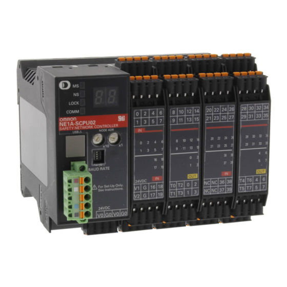
- Page 19 Section 2-1 Nomenclature and Functions NE1A-SCPU02 Node address switches: Sets the DeviceNet node address Terminal area as a 2-digit decimal number. Indicator/display area USB port (B connector) Indicator area Baud rate switch: Terminal area Sets the DeviceNet baud rate. DeviceNet communications connector: The power for communications is also supplied from this connector.
-
Page 20: Indicator/Display Areas
Nomenclature and Functions Section 2-1 2-1-2 Indicator/Display Areas Status Indicators The following LED indicators show the status of the NE1A-series Controller, network, and I/O circuits. • MS (module status) • NS (network status) • LOCK (configuration lock status) • COMM (USB communications status) •... - Page 21 Nomenclature and Functions Section 2-1 Seven-segment Display The 7-segment display indicates the NE1A-series Controller’s node address during normal conditions, and the error code and the node address of the error during error conditions. Also, “nd” is displayed during normal conditions if DeviceNet communications are disabled (i.e., Standalone Mode).
-
Page 22: Switch Settings
Section 2-1 Nomenclature and Functions 2-1-3 Switch Settings Node Address Switches Set the DeviceNet node address using the rotary switches on the front of the NE1A-series Controller. Method Two-digit decimal number Range 0 to 63 The node address is set to 63 at the factory. Note Any node address in the setting range can be used as long as the same address is not used by another node. -
Page 23: Devicenet Communications Connector
Nomenclature and Functions Section 2-1 2-1-4 DeviceNet Communications Connector Stickers are placed on the communication connectors based on the color of each communications wire. By matching the communications wire colors with the unit sticker colors, you can check to see if wires are in the correct loca- tions. -
Page 24: Input/Output Terminals And Internal Connections
Section 2-1 Nomenclature and Functions 2-1-6 Input/Output Terminals and Internal Connections NE1A-SCPU01(-V1) 24 VDC 24 VDC 24 VDC Terminal name Description Power supply terminal for internal circuits The two V0 terminals are connected internally. Power supply terminal for internal circuits The two G0 terminals are connected internally. - Page 25 Section 2-1 Nomenclature and Functions NE1A-SCPU02-V1 24 VDC 24 VDC 24 VDC Terminal name Description Power supply terminal for internal circuits The two V0 terminals are connected internally. Power supply terminal for internal circuits The two G0 terminals are connected internally. Power supply terminal for external input devices and test outputs Power supply terminal for external input devices and test outputs Power supply terminal for external output devices...
-
Page 26: Specifications
Specifications Section 2-2 Specifications This section provides the NE1A-series Controller’s specifications. 2-2-1 General Specifications NE1A-SCPU01(-V1) Item Specifications DeviceNet supply voltage 11 to 25 VDC (Supplied from communications connector.) 20.4 to 26.4 VDC (24 VDC, −15% to 10%) Device supply voltage V0 (See note.) 20.4 to 26.4 VDC (24 VDC, −15% to 10%) I/O supply voltages V1 and V2 (See note.) - Page 27 Section 2-2 Specifications NE1A-SCPU02 Item Specifications DeviceNet supply voltage 11 to 25 VDC (Supplied from communications connector.) Device supply voltage V0 (See note.) 20.4 to 26.4 VDC (24 VDC,−15% to 10%) 20.4 to 26.4 VDC (24 VDC, −15% to 10%) I/O supply voltages V1 and V2 (See note.) Current con-...
-
Page 28: Devicenet Communications Specifications
Section 2-2 Specifications 2-2-2 DeviceNet Communications Specifications Item Specifications Communications Conforms to DeviceNet. protocol Connection method The multidrop and T-branch connections can be combined (for main line and branch lines). Baud rate 500 kbits/s, 250 kbits/s, 125 kbits/s Communications Special cable with 5 lines (2 communications lines, 2 power lines, 1 shield line) medium Communications Baud rate... -
Page 29: I/O Specifications
Section 2-2 Specifications 2-2-3 I/O Specifications Safety Inputs Item Specifications Input type Current sinking (PNP) ON voltage 11 VDC min. between each input terminal and G OFF voltage 5 VDC max. between each input terminal and G OFF current 1 mA max. Input current 4.5 mA Safety Outputs... - Page 30 SECTION 3 Installation and Wiring Installation........... . 3-1-1 Requirements for Installation and Wiring .
-
Page 31: Installation
Section 3-1 Installation Installation 3-1-1 Requirements for Installation and Wiring Consider the following for installation and wiring to improve the reliability of the NE1A-series Safety Network Controller System and to fully exploit the system’s capabilities. Installation and Storage Environment Do not use or store the NE1A-series Controller in any of the following loca- tions. -
Page 32: Mounting To The Control Panel
Section 3-1 Installation 3-1-2 Mounting to the Control Panel • Use the NE1A-series Controller in an enclosure with IP54 protection or higher according to IEC/EN 60529. • Use DIN Track (TH35-7.5/TH35-15 according to IEC 60715) to mount the NE1A-series Controller in the control panel. Mount the Controller to the DIN Track using PFP-M End Plates (not included with the NE1A-series Controller) to prevent it from falling off the DIN Track because of vibration. - Page 33 Section 3-1 Installation Mounting To ensure proper ventilation, mount the NE1A-series Controller as shown in the following diagram. Bottom Do not mount the NE1A-series Controller as in the following diagrams. Bottom Bottom...
- Page 34 Section 3-1 Installation Bottom Bottom...
- Page 35 Section 3-1 Installation Position of the NE1A-SCPU01(-V1) Controller’s DIN Track Mounting Bracket DIN Track Mounting Bracket Position of the NE1A-SCPU02 Controller’s DIN Track Mounting Brackets DIN Track Mounting Brackets...
-
Page 36: Dimensions And Weight
Section 3-1 Installation 3-1-3 Dimensions and Weight Dimensions NE1A-SCPU01(-V1) - Page 37 Section 3-1 Installation NE1A-SCPU02 Weight Model Weight NE1A-SCPU01(-V1) 460 g max. NE1A-SCPU02 690 g max.
-
Page 38: Wiring
Section 3-2 Wiring Wiring 3-2-1 General Instructions on Wiring Precaution: • To prevent wire clippings from getting into the NE1A-series Controller, do not remove the label on the Controller before wiring has been completed. • After wiring has been completed, be sure to remove the label from the Controller to enable heat dissipation for proper cooling. -
Page 39: Wiring The Power Supply And I/O Lines
Section 3-2 Wiring 3-2-2 Wiring the Power Supply and I/O Lines Wire Sizes Use the following wires to connect external I/O devices to the NE1A-series Controller. Solid wire 0.2 to 2.5 mm (AWG 24 to AWG 12) Stranded (flexible) wire 0.34 to 1.5 mm (AWG 22 to AWG 16) Stranded wires should be prepared by attaching ferrules with plastic... -
Page 40: Wiring I/O Devices
Wiring Section 3-2 Reference Specifications (Product Specifications for Phoenix Contact) Model of pin Wire dimensions Pin terminal specifications terminal Cross- Stripped Overall Length of Inner Inner sectional length of length L1 metal diameter of diameter of area of insulation (mm) part L2 conductor insulative... - Page 41 Wiring Section 3-2 Devices with Mechanical Contact Outputs Examples: Emergency stop buttons and safety limit switches These devices use both a safety input terminal and test output terminal. A safety input terminal inputs the test output signal (pulse output) of the NE1A- series Controller via a contact output device.
- Page 42 Section 3-2 Wiring Controlling devices Requirements Relay with forcibly guided contacts Use approved devices with forcibly guided contacts compliant with EN 50205. For feedback, use devices with contacts capable of switching micro-loads of 4 mA at 24 VDC. Contactor Use contactors with a forcibly guided mechanism and monitor the auxiliary NC contact to detect contactor failures.
- Page 43 Wiring Section 3-2 Controlling Devices Requirements Contactor Use contactors with a forcibly guided mechanism and monitor the auxiliary NC contact to detect contactor failures. For feedback, use devices with contacts capable of switching micro-loads of 4 mA at 24 VDC. Other devices Evaluate whether devices used are appropriate to satisfy the requirements of safety category level.
- Page 44 Section 3-2 Wiring Examples of I/O Device Connections Example of Connecting an Emergency Stop Button KM1-NC KM2-NC 11 21 12 22 E1 and E2: 24-VDC power supplies S1: Emergency stop switch S2 Reset switch KM1 and KM2: Contactors Connect a 24-VDC power supply to terminals V0 and G0 (power supply termi- Note nals for internal circuits).
- Page 45 Section 3-2 Wiring Example of Connecting Two-hand Switches KM1-NC KM2-NC E1 and E2: 24-VDC power supplies S11 and S12: Two-hand switches KM1 and KM2: Contactors M: Motor Connect a 24-VDC power supply to terminals V0 and G0 (power supply termi- Note nals for internal circuits).
- Page 46 Receiver - OSSD2 (White) KM1- NC KM2- NC Emitter: +24 V (Brown) Receiver: +24 V (Brown) Emitter: 0 V (Blue), shield Light Curtain: OMRON F3SN-A Receiver: 0 V (Blue), shield Rest input (Yellow) RS-485 (Gray) External relay monitor (Red) Red: Open...
- Page 47 Section 3-2 Wiring Example of Connecting a User Mode Switch E1 and E2: 24 VDC power supplies S1: User mode switch Connect a 24-VDC power supply to terminals V0 and G0 (power supply termi- Note nals for internal circuits). This example shows an NE1A-SCPU01(-V1) Controller’s terminal layout. Note...
-
Page 48: Devicenet Wiring
Section 3-2 Wiring 3-2-4 DeviceNet Wiring Wire the DeviceNet communications cable as shown in the following diagram. Stickers are placed on the communication connectors based on the color of each communications wire. By matching the communications wire colors with the connector sticker colors, you can check to see if wires are in the correct locations. - Page 49 Section 3-2 Wiring...
- Page 50 SECTION 4 DeviceNet Communications Functions Initial Setting..........4-1-1 Hardware Setup .
-
Page 51: Initial Setting
Section 4-1 Initial Setting Initial Setting 4-1-1 Hardware Setup Node Address Setting Set the DeviceNet node address using the rotary switches on the front of the NE1A-series Controller. Method Two-digit decimal number Range 0 to 63 The node address is set to 63 at the factory. Note Any node address in the setting range can be used as long as the same address is not used by another node. - Page 52 Section 4-1 Initial Setting Baud Rate Setting The DeviceNet baud rate is set using the DIP switch on the front of the NE1A- series Controller. The baud rates settings are shown in the following table: Baud rate 125 kbit/s 250 kbit/s 500 kbit/s Software setting ON or...
-
Page 53: Software Settings
Section 4-1 Initial Setting 4-1-2 Software Settings DeviceNet Communications Disable (Standalone) Setting When DeviceNet Communications are disabled, the NE1A-series Controller stops all DeviceNet communications and operates as a Standalone Control- ler. The default is to have DeviceNet communications enabled (normal mode). Make the setting from the Network Configurator. -
Page 54: Network Status Indication
Section 4-2 Network Status Indication Network Status Indication Network status is indicated using the NS (network status) indicator on the NE1A-series Controller. The 7-segment display shows the NE1A-series Controller’s node address dur- ing normal conditions, and the error code and the node address of the error during error conditions. - Page 55 Section 4-2 Network Status Indication Seven-segment Display The 7-segment display indicates the NE1A-series Controller’s node address during normal conditions, and the error code and the node address of the error during error conditions. Also, “nd” is displayed during normal conditions if DeviceNet communications are disabled (i.e., Standalone Mode).
-
Page 56: Remote I/O Allocations
Section 4-3 Remote I/O Allocations Remote I/O Allocations 4-3-1 Remote I/O Area Allocation Overview The remote I/O areas used in Safety Masters/Slaves and Standard Masters/ Slaves are automatically allocated in the NE1A-series Controller’s I/O mem- ory according to settings made from the Network Configurator. I/O of the des- tination communications slave and the I/O area for an NE1A-series slave are displayed as I/O tags. -
Page 57: Remote I/O Area Attributes
Section 4-3 Remote I/O Allocations 4-3-2 Remote I/O Area Attributes Remote I/O Area Attributes The NE1A-series Controller’s remote I/O area has the following attributes. All values in the safety remote I/O area will be cleared if the operating mode is changed. -
Page 58: Remote I/O Area Data Configuration
Section 4-3 Remote I/O Allocations 4-3-3 Remote I/O Area Data Configuration The Network Configurator can be used to specify the data transferred by the NE1A-series Controller as Safety Slave or Standard Slave input data. This section describes the data that can be set, the setting method, and the data configuration. - Page 59 Section 4-3 Remote I/O Allocations Sample 3: Transmitting Only Status Data as Standard Slave Inputs Status Data Status A Standard Slave Status B Connection Inputs Status C Status A Status D Status C Input Data Not set up Data That Can Be Set and Example Arrangements The following table shows the data that can be set.
- Page 60 Section 4-3 Remote I/O Allocations (1) For the NE1A-SCPU01-V1, N = 2 and M = 1. For the NE1A-SCPU02, N Note = 5 and M = 2. The sizes of the local input status, test output/muting lamp status, and local input monitor status data can be specified in bytes. (2) The measures required for handling data as safety data in the data gen- eration process will not be executed for status and I/O tag data items with a non-safety attribute.
- Page 61 Section 4-3 Remote I/O Allocations Setting Example 1: Settings from Network Configurator (Unit Version 1.0 or Later) The following table shows the remote I/O area arrangement when the above settings are made. Byte Bit 7 Bit 6 Bit 5 Bit 4 Bit 3 Bit 2 Bit 1...
- Page 62 Section 4-3 Remote I/O Allocations The following table shows the remote I/O area arrangement when the above settings are made. Byte Bit 7 Bit 6 Bit 5 Bit 4 Bit 3 Bit 2 Bit 1 Bit 0 Local Input Status 1 (1 byte) Local Input Status 2 (1 byte) Local Output Status (1 byte) Bool C (1 byte)
- Page 63 Section 4-3 Remote I/O Allocations Bit Arrangements for Each Type of Data The bit arrangements for status data and I/O tag settings are shown below. Status Details The following tables show the status details. General Status (1 Byte) Attribute: Non-safety Data Content Description Input Power Supply Voltage Status...
- Page 64 Section 4-3 Remote I/O Allocations Local Input Status 1 ( 1 Byte, Controllers with Unit Version 1.0 or Later)Attribute: Safety Data Byte Bit 7 Bit 6 Bit 5 Bit 4 Bit 3 Bit 2 Bit 1 Bit 0 Safety Safety Safety Safety Safety...
- Page 65 Section 4-3 Remote I/O Allocations Test Output/Muting Lamp Status (1 Byte) (Pre-Ver. 1.0) Attribute: Non-safety Byte Bit 7 Bit 6 Bit 5 Bit 4 Bit 3 Bit 2 Bit 1 Bit 0 Test Reserved Test Test Test Test output output terminal output output...
- Page 66 Section 4-3 Remote I/O Allocations Local Input Monitor 4 ( NE1A-SCPU02 Attribute: Safety Data 1 Byte, Byte Bit 7 Bit 6 Bit 5 Bit 4 Bit 3 Bit 2 Bit 1 Bit 0 Safety Safety Safety Safety Safety Safety Safety Safety input input...
- Page 67 Section 4-3 Remote I/O Allocations I/O Tag Details The following tables show the I/O tag details. BOOL Byte Bit 7 Bit 6 Bit 5 Bit 4 Bit 3 Bit 2 Bit 1 Bit 0 Open ( =0 ) User data Bit 0 BYTE Byte...
-
Page 68: Safety Master Function
Section 4-4 Safety Master Function Safety Master Function 4-4-1 Safety I/O Communications as Safety Master Safety I/O communications are used to exchange data automatically with Safety Slaves without user programming. To perform safety I/O communications with other slaves, the following items are required: Registration of slave devices in the NE1A-series Controller. -
Page 69: Safety I/O Connection Settings
Section 4-4 Safety Master Function 4-4-2 Safety I/O Connection Settings Safety connections must be set in order to perform safety I/O communications between the NE1A-series Controller and the Safety Slaves. A “connection” is a logical communications path for a master and slave to communicate with each other. -
Page 70: Connection Type Setting
Safety Master Function Section 4-4 I/O Connection Settings Some slaves have multiple I/O data (I/O assembly data) internally and the data to be communicated from them can be selected. Here, the data to allo- cated in the NE1A-series Controller can be specified from the data in the reg- istered Safety Slave. -
Page 71: Stopping/Resetting Communications After An Error
Safety Master Function Section 4-4 EPI (Data Expected Packet Interval) Setting Set the interval to communicate safety data between the NE1A-series Safety Master and Safety Slaves. Devices that transmit data to network are moni- tored to confirm they can transmit the data within the set time interval and devices that receive data are monitored to confirm they can receive normal data within the data transmission interval using timers. - Page 72 Section 4-4 Safety Master Function Resetting a Connection Stopped due to a Communications Error When I/O communications have stopped in a connection due to a connection timeout, I/O communications can be restarted in the stopped connection by turning ON the Communications Reset Flag from the logic program or send- ing a Communications Restart command from the Network Configurator.
- Page 73 Safety Master Function Section 4-4 When these tags have been set in the logic program in advance as I/O com- munications restart conditions, I/O communications can be restarted with these tags by turning ON (OFF → ON) the specified condition.
-
Page 74: Safety Slave Function
Section 4-5 Safety Slave Function Safety Slave Function 4-5-1 Safety I/O Communications as Safety Slave An NE1A-series Controller can function as a Safety Slave. One NE1A-series Controller can function simultaneously as a Safety Master, Safety Slave, and Standard Slave. The following steps are required in order for the NE1A-series Controller to perform safety I/O communications as a Safety Slave. -
Page 75: Creating I/O Data (Safety Slave I/O) To Use As Safety Slave
Section 4-5 Safety Slave Function 4-5-2 Creating I/O Data (Safety Slave I/O) to Use as Safety Slave The I/O data to be used by the Safety Slave must be created in order for the NE1A-series Controller to perform safety I/O communications as a Safety Slave. - Page 76 Safety Slave Function Section 4-5 Safety Slave I/O Setting Set the Safety Slave I/O as follows: 1. Select the I/O type. 2. Set the I/O tags. 3. Set additional status. 4. Set additional local I/O monitor data. Safety Slave I/O NE1A (Safety Slave) Safety Slave IN Connection...
- Page 77 Section 4-5 Safety Slave Function Controllers with Unit Version 1.0 or Later Tag name Data size Attribute General Status Byte Non-safety Local Input Status 1 to N (See Byte Safety note.) Local Output Status Byte Safety Test Output/Muting Lamp Sta- Byte Non-safety tus 1 to M (See note.)
-
Page 78: Standard Slave Function
Section 4-6 Standard Slave Function Standard Slave Function 4-6-1 Standard I/O Communications as Standard Slave An NE1A-series Controller can function as a Standard Slave. One NE1A- series Controller can function simultaneously as a Safety Master, Safety Slave, and Standard Slave. The NE1A-series Controller’s internal status information is also included in the data allocated to the Standard Master, and so a monitoring system using a PLC can be established. - Page 79 Section 4-6 Standard Slave Function • Slave I/O blocks can be created for a maximum of 2 connections. • The maximum data size for Slave I/O is 16 bytes. • The following status information can be included in I/O data when the I/O type of the Slave I/O is slave input.
- Page 80 Section 4-6 Standard Slave Function Selecting Connection Type Any of the following 4 connection types can be selected. Output data cannot be set for Bitstrobe data because Bitstrobe data cannot be output from the Standard Master. Also, the maximum data size for Bitstrobe data input to Standard Master is 8 bytes.
- Page 81 Section 4-6 Standard Slave Function For the NE1A-SCPU01-V1, N = 2. For the NE1A-SCPU02, N = 5. The sizes of Note the local input status and local input monitor status data can both be specified in bytes. !WARNING Serious injury may possibly occur due to loss of required safety functions. The data attributes handled by standard I/O communications are non-safety data.
-
Page 82: Explicit Message Communications
Section 4-7 Explicit Message Communications Explicit Message Communications 4-7-1 Receiving Explicit Messages Sending explicit messages from the Standard Master to the NE1A-series Controller enables reading or writing any specified data or parameters of the Controller. The Controller operates according to the command sent from the master and returns a response. - Page 83 Section 4-7 Explicit Message Communications Class ID (Command) 0306 hex. Instance ID (Command) Explicit message Service Instance ID Read 0001 hex Read Local Input Area Read 0002 hex Read Local Output Area Read 0005 hex Read Safety Remote Input Area Read 0006 hex Read Safety Remote Output Area...
- Page 84 Section 4-7 Explicit Message Communications Number of Receive Bytes (Response) The number of bytes of receive data from the Originating Node Address to the end of the response is returned in hexadecimal. Originating Node Address (Response) The node address of the responding NE1A-series Controller is returned in 1-byte hexadecimal.
-
Page 85: Sending Explicit Messages
Section 4-7 Explicit Message Communications Error Code (Response) The following error codes defined in DeviceNet may be returned. Response Error name Cause code 08FF Service not Error in the service code. supported 13FF Not enough data The data is shorter than the specified size. 15FF Too much data The data is longer than the specified size. - Page 86 Section 4-7 Explicit Message Communications • Response data to explicit messages cannot be used in an NE1A-series Controllerís user programs. !WARNING Serious injury may possibly occur due to loss of required safety functions. Do not use explicit message data as safety data. The necessary measures for safety communications are not taken for explicit message communications.
- Page 87 Section 4-7 Explicit Message Communications...
- Page 88 SECTION 5 I/O Control Common Functions ..........5-1-1 I/O Comment Function .
-
Page 89: Common Functions
Section 5-1 Common Functions Common Functions 5-1-1 I/O Comment Function An optional name consisting of up to 32 characters can be registered in the NE1A-series Controller for each I/O terminal using the Network Configurator. These I/O comments can be used in the Function List of the Logic Editor as I/O tags, enabling easy conceptualization of what is actually being controlled and simplifying programming. -
Page 90: I/O Power Monitor
Section 5-1 Common Functions 5-1-2 I/O Power Monitor The I/O power supply input can be monitored to confirm if it is normal. If an I/O terminal on the NE1A-series Controller is set to any setting other than Not Used and the normal power supply voltage is not input, the following items will be displayed on the 7-segment display: •... - Page 91 Section 5-1 Common Functions If the alarm threshold (Threshold Maintenance Counter) is set to 0, the Con- troller will not compare the count or time PV to the alarm threshold SV. Monitoring Operations from the Network Configurator Any of the following methods can be used to monitor the number of contact operations in the local input status, test output status, or local output status.
-
Page 92: Total On Time Monitor Function
Section 5-1 Common Functions Each I/O point’s accumulated contact operations count can be cleared. To clear the count, select the contact operations count to be cleared and click the Clear Value Button. 5-1-4 Total ON Time Monitor Function Overview In NE1A-series Controllers with unit version 1.0 or later, this function times how long a local input, test output, or local output is ON and stores that total ON time internally in non-volatile memory. - Page 93 Section 5-1 Common Functions (1) The Total ON Time Monitor function (Time) and Contact Operation Note Counter function (Count) cannot be used simultaneously on one bit. Se- lect one of these functions with the Maintenance Counter Mode Choice setting. (2) When the Maintenance Counter Mode Choice setting is changed, the col- lected data (operations count or total ON time) will be cleared.
- Page 94 Section 5-1 Common Functions Setting the Total ON Time Alarm Threshold with the Network Configurator The maintenance mode (Maintenance Counter Mode Choice) and alarm threshold (Threshold Maintenance Counter) can be set for each local input, test output, and local output terminal. If the alarm threshold (Threshold Maintenance Counter) is set to 0, the Con- troller will not compare the count or time PV to the alarm threshold SV.
- Page 95 Section 5-1 Common Functions Monitoring the Total ON Time from the Network Configurator Any of the following methods can be used to monitor the total ON time in the local input status, test output status, or local output status. 1. Select the device and select Device – Maintenance information from the menubar.
-
Page 96: Safety Inputs
Section 5-2 Safety Inputs Safety Inputs 5-2-1 Overview The NE1A-SCPU01(-V1) is equipped with 16 safety input terminals. The NE1A-SCPU02 is equipped with 40 safety input terminals. By selecting the setup and wiring based on the types of input devices to be connected or the safety level to be achieved, the NE1A-series Controller can flexibly handle various applications. -
Page 97: Input Channel Mode Setting
Section 5-2 Safety Inputs 5-2-2 Input Channel Mode Setting The input channel mode of local safety inputs is set based on the type of external device to be connected. Channel Mode Description Not used Input not connected to an external device. Test pulse from test output Connects a contact output safety device with a test output. -
Page 98: Dual Channel Mode Setting
Section 5-2 Safety Inputs IMPORTANT Both input ON delays and OFF delays must be added to the I/O response per- formance. This will affect the safety distance calculation. For further details, refer to Section 9 Remote I/O Communications Perfor- mance and Local I/O Response Time. 5-2-5 Dual Channel Mode Setting An NE1A-series Controller’s local safety input terminals can be set to Dual... - Page 99 Section 5-2 Safety Inputs Normal Operation for Dual Channel Equivalent Inputs Discrepancy time Discrepancy time IN0 evaluated value IN1 evaluated value Normal IN0, IN1 status Error Operation for Dual Channel Equivalent Inputs (Discrepancy error) Discrepancy time Discrepancy time IN0 evaluated value IN0 evaluated value IN1 evaluated value IN1 evaluated value...
-
Page 100: Error Handling
Section 5-2 Safety Inputs 5-2-6 Error Handling Behavior on Error Detection Behavior in Single Channel Mode The following operations are performed if an error is detected during self-diag- nosis. • I/O tags corresponding to safety input terminals for which errors have been detected are made inactive. -
Page 101: Test Outputs
Section 5-3 Test Outputs Test Outputs 5-3-1 Test Output Mode Setting The NE1A-SCPU01(-V1) is equipped with four test output terminals. The NE1A-SCPU02 is equipped with eight test output terminals. The following settings are supported for the test outputs. Channel mode Description Not used The corresponding test output terminal is not used. -
Page 102: Safety Outputs
Section 5-4 Safety Outputs Safety Outputs 5-4-1 Overview The NE1A-SCPU01(-V1) and NE1A-SCPU02 Controllers are equipped with eight safety output terminals. By selecting the setup and wiring based on the types of external devices to be connected or the safety level to be achieved, the NE1A-series Controller can flexibly handle various applications. -
Page 103: Error Handling
Section 5-4 Safety Outputs Reflecting Output Data from Output I/O Tags to Safety Output Terminals Output I/O tag data is reflected in the safety output terminals according to the channel mode, as shown in the following tables. Channel Mode Output tag Safety output The meaning of status terminal... - Page 104 Section 5-4 Safety Outputs Error Latch Time Setting The time to latch the error state when an error occurs in a safety output circuit can be set. The error state will continue until the error latch time passes even if the cause of the error is momentarily removed. When monitoring errors from a monitoring system, take the monitoring interval into account when setting the error latch time.
- Page 105 Section 5-4 Safety Outputs...
- Page 106 SECTION 6 Programming Outline of Programming ......... 6-1-1 Outline .
-
Page 107: Outline Of Programming
Section 6-1 Outline of Programming Outline of Programming 6-1-1 Outline The NE1A-series Safety Network Controller is programmed by starting a Logic Editor from the Network Configurator. As shown below, the Logic Editor consists of a Function List where function blocks, I/O tags, and other program- ming elements are registered and a workspace where programming is actu- ally performed. - Page 108 Section 6-1 Outline of Programming Input Tags Input tags reflect the status of inputs in the following I/O areas. • Input area from the NE1A-series Controllerís local terminals • Input area from safety slaves registered as communications partners • I/O area reflected from Safety Master data •...
-
Page 109: Program Capacity
Section 6-1 Outline of Programming !WARNING Serious injury may possibly occur due to loss of required safety functions. Always verify that the safety-related signals used in safety-related logic meet applicable standards and regulations. Input only safety input signals to function blocks. -
Page 110: Function Block Overview
Function Block Overview Section 6-2 Function Block Overview Logic programming for the NE1A-series Controller is accomplished using function blocks. Various safety applications can be achieved by using the function blocks described in this section to program operation to be compliant with safety standards. -
Page 111: Function Block Editing
Function Block Editing Section 6-3 Function Block Editing Editing of function blocks can be used to set parameters, add optional I/O, and add comments according to the application. Tabs: Function block parameters Out point Setting, In/Out Settings Comments 6-3-1 Function Block Parameter Settings The following parameters can be set for function blocks depending on the user application. - Page 112 Section 6-3 Function Block Editing Setting: Dual Channel Complementary Input 1 Input 2 Output Enable (NC) (NO) Setting: Dual Channel Equivalent (2 Pairs) Input 1 Input 2 Input 3 Input 4 Output (NC) (NC) (NC) (NC) Enable Setting: Dual Channel Complementary (2 Pairs) Input 1 Input 2 Input 3...
- Page 113 Function Block Editing Section 6-3 Discrepancy Time If the function block input type is set to Dual Channel Equivalent or Dual Channel Complementary, the discrepancy time (i.e., the time between changes in the inputs) can be evaluated. The time between when one of the dual-channel inputs changes until the other one changes is monitored.
-
Page 114: I/O Settings
Section 6-3 Function Block Editing Discrepancy Error Operation Example for Dual Channel Equivalent Setting Input 1 Input 1 Input 2 Input 2 Discrepancy time Discrepancy time Output Output Enable Enable Error Discrepancy Error Discrepancy Error Normal Normal Error Synchronization Time Setting If the function block input type is set to Dual Channel Equivalent (2 Pairs) or Dual Channel Complementary (2 Pairs) for the Safety Gate Monitoring func- tion block, the synchronization time (i.e., the time between changes in the... - Page 115 Section 6-3 Function Block Editing Fault Present Setting Fault Present is a diagnostic status bit supported in some function blocks by selecting the checkbox located on the In/Out Setting or Out Point Tab Page of the function block properties. If the Fault Present checkbox is selected, an additional Fault Present output will be displayed on the function block.
-
Page 116: Command Reference: Logic Functions
Command Reference: Logic Functions Section 6-4 Command Reference: Logic Functions 6-4-1 Logic Function: NOT Diagram General Description The output will be the inverse of the input. Truth Table Input 1 Output 1 0: OFF, 1: ON 6-4-2 Logic Function: AND Diagram Default Connections General Description... - Page 117 Section 6-4 Command Reference: Logic Functions Maximum Number of Inputs for an AND Logic Function Truth Tables Truth Table for One-input AND Evaluation Input 1 Output 1 0: OFF, 1: ON Truth Table for Two-input AND Evaluation Input 1 Input 2 Output 1 0: OFF, 1: ON, x: Either ON or OFF Truth Table for Three-input AND Evaluation...
- Page 118 Section 6-4 Command Reference: Logic Functions Truth Table for Five-input AND Evaluation Input 1 Input 2 Input 3 Input 4 Input 5 Output 1 0: OFF, 1: ON, x: Either ON or OFF...
- Page 119 Section 6-4 Command Reference: Logic Functions Truth Table for Six-input AND Evaluation Input 1 Input 2 Input 3 Input 4 Input 5 Input 6 Output 1 0: OFF, 1: ON, x: Either ON or OFF Truth Table for Seven-input AND Evaluation Input 1 Input 2 Input 3...
-
Page 120: Logic Function: Or
Command Reference: Logic Functions Section 6-4 6-4-3 Logic Function: OR Diagram Default Connections General Description An OR of the input conditions will be output. Up to eight input conditions can be evaluated. Optional Input Setting The number of inputs can be increased on In/Out Setting Tab Page in the function block property dialog box. - Page 121 Command Reference: Logic Functions Section 6-4 Truth Table for Three-input OR Evaluation Input 1 Input 2 Input 3 Output 1 0: OFF, 1: ON, x: Either ON or OFF Truth Table for Four-input OR Evaluation Input 1 Input 2 Input 3 Input 4 Output 1 0: OFF, 1: ON, x: Either ON or OFF...
-
Page 122: Logic Function: Exclusive Or
Section 6-4 Command Reference: Logic Functions Truth Table for Seven-input OR Evaluation Input 1 Input 2 Input 3 Input 4 Input 5 Input 6 Input 7 Output 1 0: OFF, 1: ON, x: Either ON or OFF Truth Table for Eight-input OR Evaluation Input 1 Input 2 Input 3... -
Page 123: Logic Function: Exclusive Nor
Command Reference: Logic Functions Section 6-4 Input 1 Input 2 Output 1 0: OFF, 1: ON 6-4-5 Logic Function: Exclusive NOR Diagram General Description An exclusive NOR of the input conditions will be output. Truth Table Truth Table for Exclusive NOR Evaluation Input 1 Input 2 Output 1... - Page 124 Section 6-4 Command Reference: Logic Functions The ON status is maintained in the function block, so the Output Enable signal stays ON even if the input condition goes from ON to OFF. The signal maintained in the function block is turned OFF when the function block’s RESET condition is turned ON.
-
Page 125: Logic Function: Comparator
Section 6-4 Command Reference: Logic Functions 6-4-7 Logic Function: Comparator Diagram Output1 Input1 Default Connections General Description This function can be used only in NE1A-series Controllers with unit version 1.0 or later. The Comparator compares the specified input signals (up to 8 inputs) with the comparison value set in the configuration, and turns ON the Output 1 signal when all of the input signals match the comparison value. - Page 126 Command Reference: Logic Functions Section 6-4 Truth Table Truth Table for Comparator Evaluation (CV = Comparison Value): Input1 Input2 Input3 Input4 Input5 Input6 Input7 Input8 Output1 ≠ × × × × × × × CV for Bit 0 ≠ × ×...
- Page 127 Section 6-4 Command Reference: Logic Functions Timing Chart The horizontal broken lines in the above diagram represent the comparison values for each input. 1. Output1 turns ON when all of the input signals match the comparison val- 2. Output 1 turns OFF when any of the input signals does not match the com- parison value.
-
Page 128: Command Reference: Function Blocks
Section 6-5 Command Reference: Function Blocks Command Reference: Function Blocks 6-5-1 Function Block: Reset Diagram Reset Output Enable Monitored Input Default Connections General Description The Output Enable signal will turn ON if the Reset signal is correctly input while the input condition to the Reset function block is ON. This function block can be used to prevent the machine from automatically reset, e.g., when the power to the NE1A-series Controller is turned ON, when the operating mode is changed (from IDLE Mode to RUN Mode), or when a... - Page 129 Section 6-5 Command Reference: Function Blocks Optional Output Settings The outputs shown below can be used in the program. To enable either of these outputs, select the checkbox on the Out Point Tab Page of the function block properties dialog box. •...
- Page 130 Section 6-5 Command Reference: Function Blocks Timing Chart Reset Signal set to Low-High-Low: Monitored input Optional Input N Reset Output Enable Static Release Reset Req. Indication Idle to RUN Reset Signal set to Rising Edge: Monitored input Optional Input N Reset Output Enable...
-
Page 131: Function Block: Restart
Section 6-5 Command Reference: Function Blocks 6-5-2 Function Block: Restart Diagram Reset Output Enable Monitored Input Default Connections General Description The Output Enable signal will turn ON if the Reset signal is correctly input while the input condition to the Restart function block is ON. This function block can be used to prevent the machine from automatically restarting, e.g., when the power to the NE1A-series Controller is turned ON, when the operating mode is changed (from IDLE Mode to RUN Mode), or... - Page 132 Section 6-5 Command Reference: Function Blocks Optional Output Settings The outputs shown below can be used in the program. To enable either of these outputs, select the checkbox on the Out Point Tab Page of the function block properties dialog box. •...
-
Page 133: Function Block: Emergency Stop Pushbutton Monitoring
Section 6-5 Command Reference: Function Blocks Timing Chart Reset Signal set to Low-High-Low: Monitored input Optional Input N Reset Output Enable Static Release Reset Req. Indication Idle to RUN Reset Signal set to Rising Edge: Monitored input Optional Input N Reset Output Enable... - Page 134 Section 6-5 Command Reference: Function Blocks General Description The Emergency Stop Pushbutton Monitoring function block allows the user to monitor an emergency stop pushbutton switch. The Output Enable signal will turn ON if the input from the emergency push- button being monitored is active. The Output Enable signal will turn OFF if the input is inactive or if an error is detected for the function block.
- Page 135 Section 6-5 Command Reference: Function Blocks Truth Tables Setting: Single Channel Input 1 Output Enable (NC) 0: OFF, 1: ON Setting: Dual Channel Equivalent Input 1 Input 2 Output Enable (NC) (NC) 0: OFF, 1: ON Setting: Dual Channel Complementary Input 1 Input 2 Output...
-
Page 136: Function Block: Light Curtain Monitoring
Section 6-5 Command Reference: Function Blocks Timing Chart When Set to Dual Channel Equivalent Input1 (NC) Input2 (NC) Output Enable Discrepancy Error Fault Present Idle to RUN Discrepancy time 6-5-4 Function Block: Light Curtain Monitoring Diagram Default Connections General Description The Light Curtain Monitoring function block monitors a type-4 safety light cur- tain. - Page 137 Section 6-5 Command Reference: Function Blocks Optional Output Setting The following error output can also be used in programming. To enable this optional output, select the checkbox on the Out Point Tab Page of the function block properties dialog box. •...
-
Page 138: Function Block: Safety Gate Monitoring
Section 6-5 Command Reference: Function Blocks Error Handling and Error Resetting Error Behavior for error detection Resetting the error condition Output Fault Error output condition Enable Present Discrepancy Discrepancy Remove the cause of the error Error output: error and then do the following: (safety state) 1. - Page 139 Section 6-5 Command Reference: Function Blocks Function Tests For some safety gate applications, safeguarding devices require physical veri- fication that the device continues to operate properly (e.g., required for Cate- gory 2 safety gate applications). If the function test is enabled for the Safety Gate Monitoring function block, a safety gate test in which the safety gate must be opened and then closed again can be added as a condition for turning ON the Output Enable signal.
- Page 140 Command Reference: Function Blocks Section 6-5 Optional Output Settings The following outputs can also be used in programming. To enable any of these optional outputs, select the checkbox on the Out Point Tab Page of the function block properties dialog box. Discrepancy Error Pair 1 Discrepancy Error Pair 2 Function Test Required Signal...
- Page 141 Command Reference: Function Blocks Section 6-5 Input 1 Input 2 Output Enable (pair 1-NC) (pair 1-NO) 0: OFF, 1: ON...
- Page 142 Section 6-5 Command Reference: Function Blocks Setting: Two Dual Channel Equivalent (2 Pairs) Input 1 Input 2 Input 3 Input 4 Output (pair 1-NC) (pair 1-NC) (pair 2-NC) (pair 2-NC) Enable 0: OFF, 1: ON Setting: Two Dual Channel Complementary (2 Pairs) Input 1 Input 2 Input 3...
- Page 143 Command Reference: Function Blocks Section 6-5 Error Handling and Error Resetting Error Behavior for error detection Resetting the condition Output Fault Error output error condition Enable Present Discrepancy error at 1. Function Test Dis- Discrepancy Error Pair 1: ON pair 1 abled Remove the cause of Discrepancy error at...
-
Page 144: Function Block: Two-Hand Control
Section 6-5 Command Reference: Function Blocks Dual Channel Equivalent, Function Test Set to Disabled Input1 (NC) Input2 (NC) Output Enable Discrepancy Error Fault Present Idle to RUN Discrepancy time Discrepancy time Dual Channel Equivalent (2 pairs), Function Test Set to Disabled Input1 (Pair1-NC) Input2... - Page 145 Section 6-5 Command Reference: Function Blocks General Description The Two-hand Control function block enables monitoring the status of a two- hand switch. The Two-hand Control function block can be used with a suitable 2-hand switch to meet the requirements of type III C in EN 574, Two-hand Control Devices, Functional Aspect –...
- Page 146 Command Reference: Function Blocks Section 6-5 Truth Table Input 1 Input 2 Input 3 Input 4 Output (Pair 1-NO) (Pair 1-NC) (Pair 2-NO) (Pair 2-NC) Enable 0: OFF, 1: ON Error Handling and Error Resetting Error Behavior for error detection Resetting the error condition condition...
-
Page 147: Function Block: Off-Delay Timer
Section 6-5 Command Reference: Function Blocks Timing Chart Input1 (Pair1-NO) Input2 (Pair1-NC) Input3 (Pair2-NO) Input4 (Pair2-NC) Output Enable Discrepancy Error Pair1 Discrepancy Error Pair2 Fault Present Idle to RUN 500 ms 500 ms Discrepancy 500 ms Time 6-5-7 Function Block: OFF-delay Timer Diagram General Description The OFF-delay Timer function block performs a timer operation for an OFF... -
Page 148: Function Block: On-Delay Timer
Section 6-5 Command Reference: Function Blocks Timing Chart Input Set Value Timer Value Output Enable Idle to RUN 6-5-8 Function Block: ON-delay Timer Diagram General Description The ON-delay Timer function block performs a timer operation for an ON delay set in 10-ms increments. The range for this delay is from 0 ms to 300 s. Set Parameters Parameter Setting range... -
Page 149: Function Block: User Mode Switch
Section 6-5 Command Reference: Function Blocks 6-5-9 Function Block: User Mode Switch Diagram Default Connections General Description The User Mode Switch function block is used to monitor an operating mode switch in the user system or device. The operating mode switch that can be connected with this function block must be a 1-of-N type switch (i.e., one of N contacts is ON). - Page 150 Section 6-5 Command Reference: Function Blocks Truth Table Inputs Outputs 0: OFF, 1: ON Error Handling and Error Resetting Error condition Behavior for error detection Resetting the error condition Output Fault Present More than one input was Remove the cause ON for more than 2 s of the error.
-
Page 151: Function Block: External Device Monitoring
Section 6-5 Command Reference: Function Blocks 6-5-10 Function Block: External Device Monitoring Diagram Default Connections General Description The External Device Monitoring function block evaluates the input signal and the status of an external device and outputs safety outputs to an external device. -
Page 152: Logic Function: Routing
Section 6-5 Command Reference: Function Blocks Maximum Number of I/O for a External Device Monitoring Function Block Error Handling and Error Resetting Error Behavior for error detection Resetting the error condition Outputs 1 Fault Error output condition and 2 Present EDM feedback OFF (safety EDM Error output: ON Remove the cause of... -
Page 153: Function Block: Muting
Section 6-5 Command Reference: Function Blocks General Description The Routing function block routes one input signal to a maximum of eight out- put signals. It is used to output a signal to more than one output tag. Optional Output Settings The number of outputs can be increased on the In/Out Setting Tab Page in the function block property dialog box. - Page 154 Section 6-5 Command Reference: Function Blocks In addition, the Muting function block has an override function to forcibly turn ON the Output Enable signal without the condition for starting the muting function being satisfied. (For example, when a detection object stops in the light curtain’s detection zone, the machine can be operated to remove the detection object.) Any of the following four muting functions can be selected.
- Page 155 Section 6-5 Command Reference: Function Blocks Optional Output Settings The following outputs can also be used in programming. To enable any of these optional outputs, increase the number of outputs in the In/Out Setting Tab Page of the function block properties dialog box. •...
- Page 156 Section 6-5 Command Reference: Function Blocks is executed, the Output Enable signal will turn ON and the Fault Present signal will turn OFF. Muting Function Muting Start and Stop Conditions Reset Conditions The Output Enable is ON when all of the following conditions are met. •...
- Page 157 Section 6-5 Command Reference: Function Blocks Block Diagram Light curtain Reflected MS12 Board Workpiece Reflected MS11 Board MS11: Muting sensor connected to Muting Signal 11 MS12: Muting sensor connected to Muting Signal 12 The intersection of the two sensors must be after the light curtain. Note Muting Sequence 1.
- Page 158 Section 6-5 Command Reference: Function Blocks Timing Chart Normal Operation AOPD Input 1 (NC) AOPD Input 2 (NC) Muting Signal 11 Muting Signal 12 Output Enable Muting Status Fault Present Idle to RUN Muting time Synchronization time...
- Page 159 Section 6-5 Command Reference: Function Blocks Synchronization Error AOPD Input 1 (NC) AOPD Input 2 (NC) Muting Signal 11 Muting Signal 12 Output Enable Muting Status Synchroni- zation Error Fault Present Synchronization time Synchronization time Sequence Error AOPD Input 1 (NC) AOPD Input 2 (NC) Muting...
- Page 160 Section 6-5 Command Reference: Function Blocks Sequential Muting (Forward Direction) In this example, four Through-beam Photoelectric Sensors are set up as the sensors with intersecting detection zones. Use this configuration when the length of the workpiece being transported is longer than a fixed length. Block Diagram Light curtain MS11...
- Page 161 Section 6-5 Command Reference: Function Blocks D2 must satisfy formula 3, D3 must satisfy formula 4, and d5 must satisfy for- mula 5 in order for the muting function to operate effectively. These distance settings must prevent a passing person from enabling the muting function. Also, the light curtain and muting sensors must be setup so that a workpiece passes by all of the muting sensors before the next workpiece arrives at the muting sensors.
- Page 162 Section 6-5 Command Reference: Function Blocks Sequential Muting (Both Direction) Block Diagram 1. Entrance Light Curtain MS11 MS12 MS21 MS22 Workpiece MS11 MS12 MS21 MS22 2. Exit Light Curtain MS11 MS12 MS21 MS22 Workpiece MS11 MS12 MS21 MS22 MS11: Muting sensor connected to Muting Signal 11 MS12: Muting sensor connected to Muting Signal 12 MS21: Muting sensor connected to Muting Signal 21 MS22: Muting sensor connected to Muting Signal 22...
- Page 163 Section 6-5 Command Reference: Function Blocks Setup Distances The setup distance requirements are the same as for Sequential Muting (For- ward Direction). Timing Chart Entrance AOPD Input 1 (NC) AOPD Input 2 (NC) Muting Signal 11 Muting Signal 12 Muting Signal 21 Muting Signal 22...
- Page 164 Section 6-5 Command Reference: Function Blocks Position detection In this application, the workpiece is mounted on a machine turntable sur- rounded by a guard fence. The operator can disable the light-interruption sig- nal of the light curtain safety function in order to set a workpiece on the turntable when he is on the opposite side of the machine’s dangerous area.
- Page 165 Section 6-5 Command Reference: Function Blocks Program Example Limit switches 1 and 2 connect to Muting Signal 11 of the Muting function block by using an AND function. Limit switches 1 and 2 are set to the dual channel complementary setting for Note local inputs to evaluate the input data from the two switches.
- Page 166 Section 6-5 Command Reference: Function Blocks Override Function The Override function can turn ON the safety output ON even though the light- interruption signal of the light curtain is inactive. If a workpiece gets jammed during transit as shown in the following diagram, the system cannot be returned to normal operation without forcibly removing the workpiece.
- Page 167 Section 6-5 Command Reference: Function Blocks Stop Conditions If any of the following conditions is met, the Override function will stop and the Muting and Overriding signals will go OFF. 1. The Muting Signals are all OFF. 2. The Max. Override Time has elapsed. 3.
- Page 168 Section 6-5 Command Reference: Function Blocks Override Signal goes OFF during Override (Muting Mode: Parallel Muting with 2 Sensors) AOPD Input 1 (NC) AOPD Input 2 (NC) Override Input 1 (NO) Muting Signal 11 Muting Signal 12 Output Enable Muting Status Override Status...
-
Page 169: Function Block: Enable Switch Monitoring
Section 6-5 Command Reference: Function Blocks 6-5-13 Function Block: Enable Switch Monitoring Diagram Input1 (NO) Output Enable Input2 (NO) Default Connections General Description This function can be used only in NE1A-series Controllers with unit version 1.0 or later. The Enable Switch function block monitors the status of the enable-switch device. - Page 170 Command Reference: Function Blocks Section 6-5 Fault Present Output Setting A Fault Present output can also be used in programming. To enable this output, select the Fault Present checkbox on the Out Point Tab Page of the function block properties dialog box. Output Enable Input1 (NO) Grip Enable...
-
Page 171: Function Block: Pulse Generator
Command Reference: Function Blocks Section 6-5 6-5-14 Function Block: Pulse Generator Diagram Input Output Enable Default Connections General Description This function can be used only in NE1A-series Controllers with unit version 1.0 or later. The Pulse Generator function block generates an ON/OFF pulse output at the Output Enable signal while the function block’s Input signal is ON. -
Page 172: Function Block: Counter
Section 6-5 Command Reference: Function Blocks 6-5-15 Function Block: Counter Diagram Input Output Enable Reset Default Connections General Description This function can be used only in NE1A-series Controllers with unit version 1.0 or later. The Counter function block counts the input pulses at an input and turns ON the Output Enable signal when the count reaches a set value (SV) set with the Network Configurator. - Page 173 Command Reference: Function Blocks Section 6-5 Set Parameters Parameter Setting range Default setting Reset Condition Auto Reset Manual Reset Manual Reset Count Type Down counter (decrementing counter) Down counter (decrementing counter) Up counter (incrementing counter) Counter 1 to 65,535 (count) 1 (count) Timing Charts 1.
-
Page 174: Logic Function: Multi Connector
Section 6-5 Command Reference: Function Blocks Input 1 Input 2 Set value Count Output 1 Idle to RUN Decrementing counter: Input 1 Input 2 Set value Count Output 1 Idle to RUN 6-5-16 Logic Function: Multi Connector Diagram Input1 Output1 Default Connections General Description This function can be used only in NE1A-series Controllers with unit version... - Page 175 Section 6-5 Command Reference: Function Blocks Optional Output Settings The number of outputs can be increased on the In/Out Setting Tab Page in the function block property dialog box. Parameter Setting range Default setting Number of inputs 1 to 8 Maximum Number of outputs for a Multi Connector Logic Function Truth Tables Multi Connector Truth Table:...
- Page 176 SECTION 7 Other Functions Configuration Lock ..........Reset .
-
Page 177: Configuration Lock
Section 7-1 Configuration Lock Configuration Lock The configuration data saved in the NE1A-series Controller can be locked using the Network Configurator to protect the data after downloading and ver- ifying the configuration data. Once the configuration is locked, the configura- tion data cannot be changed until it is unlocked. -
Page 178: Reset
Section 7-2 Reset Reset 7-2-1 Reset Types The Network Configurator can reset the NE1A-series Controller in the follow- ing three ways. A password is required to enter reset. Reset type Configuration data Error history Emulate cycling power Settings before the reset Log before the reset is are retained. -
Page 179: Access Control With Password
• Locking or unlocking the configuration • Executing the NE1A-series Controller reset service • Changing the operating mode • Changing the password 7-3-2 Lost Password Contact OMRON if you lose your password and it has been set for NE1A- series Controller devices. - Page 180 SECTION 8 Operating Modes and Power Supply Interruptions NE1A-series Controller Operating Modes ......8-1-1 Operating Mode Overview .
-
Page 181: Ne1A-Series Controller Operating Modes
Section 8-1 NE1A-series Controller Operating Modes NE1A-series Controller Operating Modes 8-1-1 Operating Mode Overview The following modes are supported by the NE1A-series Controller. SELF-DIAGNOSTIC Mode The NE1A-series Controller performs self-diagnosis internally. This is required to ensure safety functions. CONFIGURING Mode CONFIGURING Mode exists while waiting for the completion of configuration from the Network Configurator. -
Page 182: Confirming The Operating Mode
Section 8-1 NE1A-series Controller Operating Modes 8-1-2 Confirming the Operating Mode Confirming with the MS Indicator The user can confirm the operating mode using the MS indicator on the front of the NE1A-series Controller. MS (module status) indicator Indicator name Color State Meaning... -
Page 183: Functions Supported In Each Operating Mode
Section 8-1 NE1A-series Controller Operating Modes 8-1-3 Functions Supported in Each Operating Mode The following table shows the conditions in each NE1A-series Controller mode and operations supported from the Network Configurator in each mode. Operating Safety functions Standard Operations from Network Configurator z mode functions (See note 1.) -
Page 184: Operating Mode Setting At Startup
Section 8-1 NE1A-series Controller Operating Modes 8-1-4 Operating Mode Setting at Startup The user can select the NE1A-series Controller’s operating mode from the fol- lowing two modes at startup, after the normal completion of configuration. Operating mode Description on startup Normal Mode The NE1A-series Controller starts in IDLE Mode after configuration has been completed. -
Page 185: Behavior For Power Supply Interruptions
Section 8-2 Behavior for Power Supply Interruptions Behavior for Power Supply Interruptions 8-2-1 Behavior in Voltage Drop Low Power Supply Voltage for the Internal Circuits If the power supply voltage for the internal circuit drops to 85% of the rated voltage or lower, the NE1A-series Controller will turn OFF the outputs. - Page 186 SECTION 9 Remote I/O Communications Performance and Local I/O Response Time Outline............Operational Flow and Cycle Time .
-
Page 187: Outline
Section 9-1 Outline Outline The NE1A-series Controller’s remote I/O communications performance and local I/O response time are described in this section. The calculations shown here are assumed to satisfy the following conditions: • The configuration is correct. • The power has been turned ON, the SNC self-diagnostic function has been completed, and the NE1A-series Controller is in RUN Mode. -
Page 188: Operational Flow And Cycle Time
Section 9-2 Operational Flow and Cycle Time Operational Flow and Cycle Time The NE1A-series Controller’s operations are outlined here. The NE1A-series Controller initializes itself internally when the power is turned ON. Unless there are errors, the Controller then cyclically executes system processing, DeviceNet/USB communications processing, I/O refreshing, and user pro- gram. - Page 189 Section 9-2 Operational Flow and Cycle Time lish the above connection has been completed until enabled I/O data is sent and received using that connection. (Processing time after the connection is established until enabled safety I/O data is sent and received) = EPI setting x 3 + NE1A-series Controller cycle time x 6 After the NE1A-series Controller is initialized, it will be added to the DeviceNet Note...
-
Page 190: I/O Refresh Cycle Time And Network Reaction Time
Section 9-3 I/O Refresh Cycle Time and Network Reaction Time I/O Refresh Cycle Time and Network Reaction Time The I/O refresh cycle time and network reaction time parameters are required to evaluate local I/O response and I/O communications performance for the NE1A-series Controller. - Page 191 Section 9-3 I/O Refresh Cycle Time and Network Reaction Time The network reaction time The network reaction time of the NE1A-series Controller is used when calcu- lating the remote I/O reaction time. The network reaction time can be checked on the Safety Connections Tab Page of the Edit Device Parameters Window.
-
Page 192: Reaction Time
The reaction time is used to calculate the safety distance. The reaction time is calculated for each safety chain. Some typical safety chains are shown below. 1. Local Input - Local Output Safety NE1A Series Actuator sensor/switch 2. Remote Input - Local Output Safety... - Page 193 Section 9-4 Reaction Time 3. Local Input - Remote Output Safety sensor/ NE1A Series Safety I/O Terminal Actuator switch Local input/ Output Network Sensor/switch Actuator remote output reaction reaction reaction time reaction time reaction time (F) time (G) timeC (C) 4.
- Page 194 Section 9-4 Reaction Time The cycle times read by the Network Configurator will be as follows: Controller cycle time = 4 ms I/O refresh cycle time = 4 ms The cycle time of the NE1A-SCPU02 is 6 ms and the I/O refresh time is 6 ms. The reaction time is obtained using the following equation: Reaction time (ms) = Switch reaction time + NE1A-SCPU01 local input/local output reaction time...
- Page 195 Section 9-4 Reaction Time The network reaction time will be 24 ms based on a safety connection EPI of 6 ms. The reaction time is obtained using the following equation: Reaction time (ms) = Switch reaction time + Safety I/O Terminal input reaction time + Network reaction time + NE1A-SCPU01 remote input/local output reaction time + Actuator reaction time...
- Page 196 Section 9-4 Reaction Time The node 2 (#2) cycle times will be as follows: NE1A-SCPU01 cycle time = 7 ms I/O refresh cycle time = 3.5 ms The network reaction time will be 28 ms based on a safety connection EPI of 7 ms.
-
Page 197: Verifying The Reaction Time
Section 9-4 Reaction Time Network reaction times #1 and #2 will be 24 ms each, based on a safety con- nection EPI of 6 ms. The reaction times are obtained using the following equa- tion: Reaction time (ms) = Switch reaction time + Safety I/O Terminal input reaction time + Network reaction time #1 + NE1A-SCPU01 remote input/remote output reaction time... - Page 198 SECTION 10 Troubleshooting 10-1 Error Categories ..........10-2 Confirmation of Error State .
-
Page 199: Error Categories
Section 10-1 Error Categories 10-1 Error Categories NE1A-series Controller errors can be categorized into the following three cat- egories: Nonfatal Errors The part where an error has occurred stops at each local I/O or safety I/O connection terminal and places it in the safety state. The Controller, however, continues in RUN Mode. -
Page 200: Confirmation Of Error State
Section 10-2 Confirmation of Error State 10-2 Confirmation of Error State Error details can be checked from the following two pieces of information: • LED indicator status on the front of the NE1A-series Controller • Reading the NE1A-series Controllerís error history using the Network Configurator... -
Page 201: Indicator/Display Status And Corrective Actions For Errors
Section 10-3 Indicator/Display Status and Corrective Actions for Errors 10-3 Indicator/Display Status and Corrective Actions for Errors Critical Errors Indicators/display Error history Seven- Name Saved in Cause Corrective actions segment nonvolatile display memory None Not sup- • Noise level higher than Cycle the power supply and ported expected. - Page 202 Section 10-3 Indicator/Display Status and Corrective Actions for Errors Indicators/display Error history Cause Corrective actions Seven- Name Saved in segment nonvola- display tile memory Standard I/O See note Standard I/O Check the following points: Connection connection Master node • Make sure the baud rate is the Timeout timeout address...
- Page 203 Section 10-3 Indicator/Display Status and Corrective Actions for Errors Indicators/display Error history Cause Corrective actions Seven- Name Saved in segment nonvola- display tile memory terminal External Test See note External wiring Check the following points: Signal Failure at error in safety Node •...
- Page 204 Section 10-3 Indicator/Display Status and Corrective Actions for Errors Indicators/display Error history Cause Corrective actions Seven- Name Saved in segment nonvola- display tile memory Target ter- Over Current See note Overcurrent was Check the following points: minal Detected at Safety detected at Node •...
- Page 205 Section 10-3 Indicator/Display Status and Corrective Actions for Errors Indicators/display Error history Cause Corrective actions Seven- Name Saved in segment nonvola- display tile memory Input PS Voltage See note I/O power Check the following points: (input) is not con- Node •...
-
Page 206: Error History
Section 10-4 Error History 10-4 Error History The error history records errors that the NE1A-series Controller detects in the total operating time of the Controller. The error history can be read from the Network Configurator. 10-4-1 Error History Table Error History Table When an error is detected in a Pre-Ver. - Page 207 Section 10-4 Error History The NE1A-series Controller’s error histories are read by the Network Configu- rator as shown below. The time when an error occurs (total operating time) 1 record in the error history Status information when an Node address of an error device error occurs...
-
Page 208: Error Information Details
Section 10-4 Error History 10-4-2 Error Information Details Message Corrective Actions NE1A-series Controller System Failures System Failure System failure Replace the unit if the system failure still occurs after turning ON the power supply again. Invalid Configuration Configuration invalid Configuration differs from the original configuration. Reconfigure after checking. - Page 209 Section 10-4 Error History Message Corrective Actions NE1A-series Controller System Failures EM Transmission Error Unable to transmit Check the following points: because the destination (Destination Device • Node address of the destination node device is not on the Absence) • Node address of the transmission message network.
- Page 210 Error History Section 10-4 Message Corrective Actions NE1A-series Controller System Failures Over Current Detected Overcurrent was detected Check the following points: at Safety Output at safety output. • Make sure there is no overcurrent for the output. • Make sure the output signal wire does not have an earth fault. Short Circuit Detected at Short circuit was detected •...
-
Page 211: Errors When Downloading
Errors When Downloading Section 10-5 10-5 Errors When Downloading 10-5-1 Outline An NE1A-series Controller or other Safety Device may return an error when configuration data is downloaded to them. The cause of the error can be determined from the error information displayed on the Network Configurator. 10-5-2 Error Messages and Countermeasures Message displayed on the Network Countermeasure... - Page 212 Section 10-5 Errors When Downloading Message displayed on the Network Countermeasure Configurator An error was found during parameter 1. There is a non-alignment between configuration parameters. Check the following check. items and change the parameters. • The time parameters (e.g., Discrepancy Time) set for function blocks in the NE1A- series Controllerís settings is shorter than the Controllerís cycle time.
- Page 213 Errors When Downloading Section 10-5 Message displayed on the Network Countermeasure Configurator Connection failed. Tried to configure a device on the DeviceNet network via the NE1A-series Controller’s USB port, but connection failed. Check that power is turned ON to the device and download again.
-
Page 214: Errors When Resetting
Section 10-6 Errors When Resetting 10-6 Errors When Resetting 10-6-1 Outline The NE1A-series Controller may return an error response when it is reset. The messages displayed on the Network Configurator can be used to identify and correct the error. 10-6-2 Error Messages and Countermeasures Message displayed on the Countermeasures Network Configurator... -
Page 215: Errors When Changing Modes
Section 10-7 Errors When Changing Modes 10-7 Errors When Changing Modes 10-7-1 Outline The NE1A-series Controller may return an error response when its operating mode is being changed. The messages displayed on the Network Configura- tor can be used to identify and correct the error. 10-7-2 Error Messages and Countermeasures Message Displayed on the Network Countermeasures... -
Page 216: Connection Status Tables
Connection Status Tables Section 10-8 10-8 Connection Status Tables 10-8-1 Outline If an error occurs when the NE1A-series Controller tries to establish a safety connection with a DST1-series Safety I/O Terminal or an NE1A-series Con- troller set as a Slave, the 7-segment display will display the error code “d6” or “d5”. -
Page 217: Connection Status For Dst1 Series
Section 10-8 Connection Status Tables 10-8-2 Connection Status for DST1 Series Status Countermeasure 00:0001 Normal communications The Safety I/O connection status is normal. 01:0001 Safety I/O Connection The Safety I/O connection has timed out. Check the following items. Timeout • Do all nodes have the same baud rate? •... - Page 218 Section 10-8 Connection Status Tables Status Countermeasure 01:0117 Connection Path Error 1. Two or more output safety I/O connections have been set for the Safety Slave. • Change the Safety Connection setting for the Safety Master so there is only one connection. Then reset the Safety Slave to default settings and download the device parameters to the Safety Slave again.
-
Page 219: Connection Status For The Ne1A-Series Controller (Safety Slave Function)
Section 10-8 Connection Status Tables 10-8-3 Connection Status for the NE1A-series Controller (Safety Slave Function) Status Countermeasures 00:0001 Normal communications The Safety I/O connection status is normal. 01:0001 Safety I/O Connection The Safety I/O connection has timed out. Check the following items. Timeout •... - Page 220 Connection Status Tables Section 10-8 Status Countermeasures 01:0117 Connection Path Error Two ore more single-cast safety I/O connections or a multi-cast safety I/O connection with a different EPI has been set for a safety slave I/O. • To share one safety slave I/O on a Safety Slave with more than one Safety Master, make the EPI all the same and set the connection type to Multi-cast.
- Page 221 Connection Status Tables Section 10-8...
- Page 222 SECTION 11 Maintenance and Inspection 11-1 Inspection ........... . 11-2 NE1A-series Controller Replacement.
- Page 223 Inspection Section 11-1 11-1 Inspection To use an NE1A-series Controller’s functions in the best condition, daily or periodical inspection must be performed. • Check that the NE1A-series Controller is used within the range of specifi- cations. • Check that installation conditions and wiring of the NE1A-series Control- ler are proper.
- Page 224 • When returning the defective unit for repair, attach a sheet of paper to the unit describing in as much detail as possible the defect. Send the unit to the OMRON branch or sales office listed in the back of this operation manual.
- Page 225 Section 11-2 NE1A-series Controller Replacement...
- Page 226 Appendix A Appendix 1: Application and Configuration Examples A-1-1 Emergency Stop Application: Dual Channel Mode with Manual Reset Wiring Diagram KM1-NC KM2-NC 11 21 12 22 E1 and E2: 24-VDC power supplies S1: Emergency stop pushbutton S2: Reset Switch KM1 and KM2: Contactors (1) Connect a 24-VDC power supply to terminals V0 and G0 (power supply terminals for internal cir- Note cuits).
- Page 227 Appendix A Timing Diagram Emergency stop button Emergency stop button pressed. (ESTOP) pressed. ESTOP 11-12 ESTOP 21-22 More than More than 350 ms 350 ms Reset Feedback Idle to Programming Example...
- Page 228 Appendix A Local Input and Test Output Setting Example Local Output Setting Example...
- Page 229 Appendix A A-1-2 Safety Gate Application: Dual Channel Mode Limit Switches with Automatic Reset Wiring Example Open KM1-NC KM2-NC E1 and E2: 24-VDC power supplies S1: Safety limit switch S2: Limit switch (normal open contact) KM1 and KM2: Contactors (1) Connect a 24-VDC power supply to terminals V0 and G0 (power supply terminals for internal Note circuits).
- Page 230 Appendix A Programming Example Local Input and Test Output Setting Example...
- Page 231 Appendix A Local Output Setting Example...
- Page 232 Appendix A A-1-3 Safety Gate Application: Dual Channel Door Switches with Automatic Reset and Dual Channel Emergency Stop Switch with Manual Reset Wiring Example E1 and E2: 24-VDC power supply S1: Emergency stop pushbutton Open S2: Reset Switch Open S3 and S5:Safety limit switch S4 and S6: Limit switch KM1, KM2, KM3, and KM4: Contactors 11 21...
- Page 233 Appendix A Programming Example Local Input and Test Output Setting Example...
- Page 234 Appendix A Local Output Setting Example...
- Page 235 Appendix A A-1-4 Safety Light Curtain: Dual Channel Safety Light Curtain with Manual Reset and Dual Channel Emergency Stop Switch with Manual Reset Wiring Example Emitter Receiver F 3W9 -JC@A-D F39-JC@A-L RS-485(A) (Gray ) RS-485(B) (Pink) KM1-NC KM2-NC NE1A-SCPU01(-V1) E1 and E2: 24-VDC power supply S1: Reset switch S2: Reset switch S3: Emergency stop pushbutton...
- Page 236 Appendix A Timing Diagram Emergency stop button (ESTOP) pressed. 350 ms min. 350 ms min. ESTOP RESET KM1,2 Feedback Idle to RUN : Feedback time Programming Example...
- Page 237 Appendix A Local Input and Test Output Setting Example Local Output Setting Example...
- Page 238 Appendix A A-1-5 Safety Mat: Dual Channel Safety Mat with Manual Reset and Dual Channel Emergency Stop Switch with Manual Reset Wiring Example Black E1 and E2: 24-VDC power supply White S1: Reset switch S2: Emergency stop pushbutton KM1 and KM2: Contactors Auto reset White Black...
- Page 239 Appendix A Programming Example Local Input and Test Output Setting Example...
- Page 240 Appendix A Local Output Setting Example...
- Page 241 Appendix A Appendix 2: Calculated Values of PFD and PFH Calculated values of PFD and PFH for the NE1A-series Controller are given in the following tables. These val- ues must be calculated for the overall devices within the system to comply with the SIL required for application. A-2-1 Calculated PFD Values Model...
- Page 242 Appendix A Appendix 3: DeviceNet Explicit Messages User-specified NE1A parameters can be read and written by sending DeviceNet explicit messages to the NE1A-series Controller. The NE1A-series Controller will process the received messages and return responses. This appendix describes the messages that are supported by the NE1A-series Controller. A-3-1 Explicit Messages: NE1A-SCPU01-V1 Reading General Status: NE1A-SCPU01-V1...
- Page 243 Appendix A Setting and Monitoring Safety Input Terminals: Inputs (NE1A-SCPU01-V1) Explicit Service Function Command Response message Service Class Data size code stance tribute Monitor Mode for Read Reads the monitor mode of 0E hex 01 to 10 65 hex 1 byte Terminal Mainte- maintenance information for 00 hex: Total ON time...
- Page 244 Appendix A Setting and Monitoring Safety Output Terminals: Outputs (NE1A-SCPU01-V1) Explicit Service Function Command Response message Service Class Data size code stance tribute Monitor Mode for Read Reads the monitor mode of 0E hex 01 to 08 65 hex 1 byte Terminal Mainte- maintenance information for 00 hex: Total ON time...
- Page 245 Appendix A Monitoring Test Output Terminals: NE1A-SCPU01-V1 Explicit Service Function Command Response message Service Class Data size code stance tribute Monitor Mode for Read Reads the monitor mode of 0E hex 01 to 04 83 hex 1 byte Terminal Mainte- maintenance information of the 00 hex: Total ON time nance Information...
- Page 246 Appendix A A-3-2 Explicit Messages: NE1A-SCPU02 Reading General Status: NE1A-SCPU02 Explicit Service Function Command Response message Service Class Data size code stance tribute Read Unit General Read Reads the Unit’s general 0E hex 39 hex 01 hex 6E hex 1 byte Status status.
- Page 247 Appendix A Setting and Monitoring Safety Input Terminals: Inputs (NE1A-SCPU02) Explicit Service Function Command Response message Service Class Data size code stance tribute Monitor Mode for Read Reads the monitor mode of 0E hex 01 to 28 65 hex 1 byte Terminal Mainte- maintenance information for 00 hex: Total ON time...
- Page 248 Appendix A Setting and Monitoring Safety Output Terminals: Outputs (NE1A-SCPU02) Explicit Service Function Command Response message Service Class Data size code stance tribute Monitor Mode for Read Reads the monitor mode of 0E hex 01 to 08 65 hex 1 byte Terminal Mainte- maintenance information for 00 hex: Total ON time...
- Page 249 Appendix A Monitoring Test Output Terminals: NE1A-SCPU02 Explicit message Service Function Command Response Service Class Data size code stance tribute Monitor Mode for Read Reads the monitor mode of 0E hex 01 to 08 83 hex 1 byte Terminal Mainte- maintenance information for the 00 hex: Total ON time nance Information...
- Page 250 Appendix A A-3-3 Explicit Messages: NE1A-SCPU01 Reading General Status: NE1A-SCPU01 Explicit message Service Function Command Response Service Class Data size code stance tribute Read Unit General Read Reads the Unit’s general 0E hex 39 hex 01 hex 6E hex 1 byte Status status.
- Page 251 Appendix A Setting and Monitoring Safety Output Terminals: Outputs (NE1A-SCPU01) Explicit message Service Function Command Response Ser- Class Data size vice stance trib- code ute ID Read Safety Read Reads the normal flag status 0E hex 01 to 05 hex 1 byte Output Normal of the number (1 to 8) speci-...
- Page 252 Glossary Term Definition assembly Internal data in a device gathered as one group to be accessed externally. Busoff Status that occurs when the error rate is extremely high over a communica- tions cable. An error is detected when the internal error counter exceeds a certain thresh- old value.
- Page 254 Index dual channel complementary (2 pairs) dual channel equivalent abort dual channel equivalent (2 pairs) abort errors dual channel mode setting ABORT State abort status access control automatic baud rate detection emergency stop pushbutton monitoring Enable Switch EPI (data expected packet interval) setting error detected during self-diagnosis baud rate setting error history...
- Page 255 Index I/O type network reaction time IDLE Mode network status IN 0 to 15 node address duplication IN 0 to 39 node address duplication error input and output size settings node address setting input channel mode node address switches input OFF delays nomenclature input ON delays nonfatal errors...
- Page 256 Index remote I/O area attributes standards Remote I/O Area Data Configuration supported function blocks reset synchronization time setting reset types system configuration resetting errors restart routing test output mode RS-FF Test Output/Muting Lamp Status RUN Mode test outputs test source total ON time alarm threshold safety chain total ON time monitor...
- Page 257 Index...
- Page 258 Revision History A manual revision code appears as a suffix to the catalog number on lower left corners of the front and back covers of the manual. Cat. No. Z906-E2-03 Revision code The following table outlines the changes made to the manual during each revision. Page numbers refer to the previous version.
Need help?
Do you have a question about the NE1A Series and is the answer not in the manual?
Questions and answers