MSI MS-7043 User Manual
Atx mainboard
Hide thumbs
Also See for MS-7043:
- User manual (30 pages) ,
- User manual (94 pages) ,
- User manual (90 pages)
Table of Contents
Advertisement
Advertisement
Table of Contents

Subscribe to Our Youtube Channel
Related Manuals for MSI MS-7043


Summary of Contents for MSI MS-7043
- Page 1 PT880 Neo (V2.0) MS-7043 (v1.X) ATX Mainboard English Version G52-M7043X5...
-
Page 2: Fcc-A Radio Frequency Interference Statement
VOIR LA NOTICE D’INSTALLATION AVANT DE RACCORDER AU RESEAU. Micro-Star International MS-7043 This device complies with Part 15 of the FCC Rules. Operation is subject to the following two conditions: (1) this device may not cause harmful interference, and (2) this device must accept any interference received, including interference that may cause undesired operation. -
Page 3: Copyright Notice
If a problem arises with your system and no solution can be obtained from the user’s manual, please contact your place of purchase or local distributor. Alternatively, please try the following help resources for further guidance. Visit the MSI website for FAQ, technical guide, BIOS updates, driver updates, and other information: faq/esc_faq_list.php Contact our technical staff at: http://www.msi.com.tw/program/service/faq/... -
Page 4: Safety Instructions
Safety Instructions Always read the safety instructions carefully. Keep this User’s Manual for future reference. Keep this equipment away from humidity. Lay this equipment on a reliable flat surface before setting it up. The openings on the enclosure are for air convection hence protects the equip- ment from overheating. -
Page 5: Table Of Contents
Safety Instructions ... v Chapter 1. Getting Started ... 1-1 Mainboard Specifications ... 1-2 Mainboard Layout ... 1-4 MSI Special Features ... 1-5 Color Management ... 1-5 CoreCenter ... 1-6 Core CellTM Chip ... 1-8 Round Cable (Optional) ... 1-9 CPU Thermal Protection ... - Page 6 Front Panel Audio Connector: JAUD1 ... 2-13 Chassis Intrusion Switch Connector: JCI1 (Optional) ... 2-14 Front Panel Connectors: JFP1 & JFP2 ... 2-14 CD-In Connector: JCD1 ... 2-15 D-Bracket™ 2 Connector: JDB1 (Optional) ... 2-15 S-Bracket (SPDIF) Connector: JSP1 (Optional) ... 2-16 Front USB Connectors: JUSB1 &...
- Page 7 Information ... A-6 Using 2-, 4- & 6- Channel Audio Function ... A-7 Appendix B: VIA VT8237 Serial ATA RAID ... B-1 Introduction ... B-2 BIOS Configuration ... B-4 Installing RAID Software & Drivers ... B-14 Using VIA RAID Tool ... B-17...
-
Page 8: Chapter 1. Getting Started
Chapter 1. Getting Started Getting Started Thank you for choosing the PT880 Neo (V2.0) (MS-7043) v1.X ATX mainboard. The PT880 Neo (V2.0) is a superior computer mainboard based on VIA Southbridge for optimal system efficiency. Designed to fit the ad- vanced Intel ®... -
Page 9: Mainboard Specifications
MS-7043 ATX Mainboard Mainboard Specifications ® Supports Intel P4 Northwood/Prescott (Socket 478) processors FSB 400 (for Northwood only), 533, 800MHz Supports up to 3.4GHz or higher speed (Please refer to the latest online news at h t t p : / / w w w . m s i . c o m . t w / p r o g r a m / p r o d u c t s / m a i n b o a r d / m b d / pro_mbd_cpu_support.php) -
Page 10: Getting Started
On-Board Peripherals On-Board Peripherals include: - 1 floppy port supports 2 FDDs with 360K, 720K, 1.2M, 1.44M and 2.88Mbytes - 1 serial port (COM A) - 1 parallel port supports SPP/EPP/ECP mode - 8 USB 2.0 ports (Rear x 4 / Front x 4) - 1 RJ45 LAN jack - 1 D-Bracket2 pinheader (Optional) - 1 S-Bracket pinheader (Optional) -
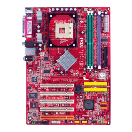
Page 11: Mainboard Layout
Line-In Line-Out B: Mic VT6122 Gigabit LAN Winbond W83697HF BIOS VT1617 Audio Codec JCD1 JAUD1 JSP1 PT880 Neo (V2.0) (MS-7043 v1.X) ATX Mainboard CPUFA1 PT880 AGP1 PCI 1 BATT PCI 2 PCI 3 VT8237 PCI 4 PCI 5 JUSB1 JUSB2... -
Page 12: Msi Special Features
MSI Special Features Color Management MSI has a unified color management rule for some connectors on the mainboards, which helps you to install the memory modules, expansion cards and other peripherals devices more easily and conveniently. Dual Memory DDR DIMMs: Channel A is light green, Channel B is purple... -
Page 13: Corecenter
MS-7043 ATX Mainboard CoreCenter CoreCenter - contains OC Menu panel, users can determine their processor and memory type to optimize its memory capacity. This all-in-one hardware console is advanced combination of the popular PC Alert and Fuzzy Logic. Including powerful... - Page 14 OC Menu The exclusive OC Menu is fully developed to support DDR400+ memory modules. By comprehensive validation of over 67 DDR400+ memory modules, MSI concluded best parameters for DRAM voltage, Vio and other BIOS settings. You can select DDR433, DDR450, DDR466 and DDR500 from DRAM frequency in BIOS setting. Or you can just click on OC Menu button to configure in the OC Menu at CoreCenter.
-
Page 15: Core Celltm Chip
MS-7043 ATX Mainboard Core CellTM Chip By diagnosing the current system utilization, the CoreCell™ Chip automatically tunes your motherboard to the optimal state, leading to less noise, longer duration, more power-saving and higher performance. Features of CoreCell™ PowerPro -- Saves up to 65% power. -
Page 16: Round Cable (Optional)
(FDD1) and the other end to the standard flooy disk. CPU Thermal Protection Aimed to prevent the CPU from overheating, MSI has developed a CPU Thermal Protection mechanism for Intel ® CPU platform. This CPU Thermal Protection mechanism works on a thermal signal sensor. If the mechanism senses an abnormal temperature rise, it will automatically shut down the system and the CPU temperature will then drop down and resume normal. -
Page 17: Live Bios™/Live Driver
BIOS/drivers online so that you don’t need to search for the correct BIOS/driver version throughout the whole Web site. To use the function, you need to install the “MSI Live Update 3” application. After the installation, the “MSI Live Update 3” icon (as shown on the right) will appear on the screen. -
Page 18: Live Monitor
BIOS/drivers version on the MSI Web site. To use the function, you need to install the “MSI Live Update 3” application. After installation, the “MSI Live Monitor” icon (as shown on the right) will appear on the screen. Double click this icon to run the application. -
Page 19: D-Bracket™ 2 (Optional)
MS-7043 ATX Mainboard D-Bracket™ 2 (Optional) D-Bracket™ 2 is a USB bracket integrating four Diagnostic LEDs, which use graphic signal display to help users understand their system. The LEDs provide up to 16 combinations of signals to debug the system. The 4 LEDs can detect all problems that fail the system, such as VGA, RAM or other failures. - Page 20 D-Bracket™ 2 Processor Initialization - This will show information regarding the processor (like brand name, system bus, etc...) Testing RTC (Real Time Clock) Initializing Video Interface - This will start detecting CPU clock, checking type of video onboard. Then, detect and initialize the video adapter.
-
Page 21: S-Bracket (Optional)
MS-7043 ATX Mainboard S-Bracket (Optional) S-Bracket is a bracket which provides 2 SPDIF jacks for digital audio transmis- sion and 2 analog Line-Out connectors for additional 4-channel analog audio output. With the S-Bracket, your system will be able to perform 6-channel audio operation for wonderful surround sound effect, or connect to Sony &... -
Page 22: Chapter 2. Hardware Setup
Chapter 2. Hardware Setup Hardware Setup This chapter provides you with the information about hard- ware setup procedures. While doing the installation, be careful in holding the components and follow the installation procedures. For some components, if you install in the wrong orientation, the compo- nents will not work properly. -
Page 23: Quick Components Guide
MS-7043 ATX Mainboard Quick Components Guide JPW1, p.2-9 Back Panel I/O, p.2-10 AGP1, p.2-19 PCI 1~5, p.2-19 JAUD1, p.2-13 JCD1, p.2-15 JSP1, p.2-16 CPUFA1, p.2-13 CPU, p.2-3 DIMM1~3, p.2-7 JDB1, p.2-15 JUSB1/2, p.2-17 ATX1, p.2-9 FDD1, p.2-11 IDE2/1, p.2-11 JBAT1, p.2-18 SATA2/1, p.2-12... -
Page 24: Central Processing Unit: Cpu
CPU from overheating. Overclocking This motherboard is designed to support overclocking. However, please make sure your components are able to tolerate such abnormal settings while doing overclocking. Any attempt to operate beyond product specifications is not recommended. -
Page 25: Cpu Installation Procedures For Socket 478
MS-7043 ATX Mainboard CPU Installation Procedures for Socket 478 1. Please turn off the power and unplug the power cord before installing the CPU. 2. Pull the lever sideways away from the socket. Make sure to raise the lever up to a 90-de- gree angle. -
Page 26: Installing The Cpu Fan
Installing the CPU Fan As processor technology pushes to faster speeds and higher performance, thermal management becomes increasingly important. To dissipate heat, you need to attach the CPU cooling fan and heatsink on top of the CPU. Follow the instructions below to install the Heatsink/Fan: 1. - Page 27 MS-7043 ATX Mainboard 5. Connect the fan power cable from the mounted fan to the 3-pin fan power connector on the board. fan power cable MSI Reminds You... Please refer to the Intel/AMD websites for recommended CPU cooling fans.
-
Page 28: Memory
The mainboard provides 3 slots for 184-pin, 2.5V DDR DIMM and supports up to 3GB memory size. You can install DDR266 / DDR333 / DDR400 / DDR433 / DDR466 SDRAM modules on the DDR DIMM slots (DIMM 1~3). To operate properly, at least one DIMM module must be installed. Please note that DDR433/DDR466 are overclocking specs. -
Page 29: Installing Ddr Modules
MS-7043 ATX Mainboard Memory modules can be installed in any combination as follows: DIMM1 DIMM2 128MB~1GB 128MB~1GB 128MB~1GB 128MB~1GB 128MB~1GB 128MB~1GB 128MB~1GB 128MB~1GB Please refer to http://www.msi.com.tw/program/products/mainboard/ mbd/pro_mbd_trp_list.php Installing DDR Modules The DDR DIMM has only one notch on the center of module. The module will only fit in the right orientation. -
Page 30: Power Supply
This 12V power connector is used to provide power to the CPU. JPW1 JPW1 Pin Definition SIGNAL MSI Reminds You... 1. Power supplies of 300watt (and up) are highly recommended for sys- tem stability. 2. Please refer to the Intel/AMD websites for recommended power supplies. -
Page 31: Back Panel
MS-7043 ATX Mainboard Parallel Mouse Keyboard COMA Mouse/Keyboard Connector Pin4 VCC Serial Port 1 2 3 4 5 6 7 8 9 USB Ports SIGNAL -Data +Data 2-10 Back Panel SPDIF Out USB Ports Pin5 Mouse/KBD Clock Pin6 NC Pin3 GND... -
Page 32: Floppy Disk Drive Connector: Fdd1
IDE2 (Secondary IDE Connector) IDE2 can also connect a Master and a Slave drive. MSI Reminds You... If you install two hard disks on cable, you must configure the second drive to Slave mode by setting its jumper. Refer to the hard disk docu- mentation supplied by hard disk vendors for jumper setting instructions. -
Page 33: Serial Ata Raid 0, 1 Connectors: Sata1, Sata2
MS-7043 ATX Mainboard Serial ATA RAID 0, 1 Connectors: SATA1, SATA2 ® The southbridge VIA independent SATA ports for support of up to two Serial ATA (Serial ATA RAID) drives and supports RAID levels 0 and 1 for easy management of the storage subsystems. -
Page 34: Fan Power Connector: Cpufa1
GND. If the mainboard has a System Hardware Monitor chipset onboard, you must use a specially designed fan with speed sensor to take advantage of the CPU fan control. MSI Reminds You... Always consult the vendors for proper CPU cooling fans. Front Panel Audio Connector: JAUD1... -
Page 35: Chassis Intrusion Switch Connector: Jci1 (Optional)
MS-7043 ATX Mainboard Chassis Intrusion Switch Connector: JCI1 (Optional) This connector is connected to a 2-pin chassis switch. If the chassis is opened, the switch will be short. The system will record this status and show a warning message on the screen. To clear the warning, you must enter the BIOS utility and clear the record. -
Page 36: Cd-In Connector: Jcd1
CD-In Connector: JCD1 The connector is for CD-ROM audio connector. D-Bracket™ 2 Connector: JDB1 (Optional) The mainboard comes with a JDB1 connector for you to connect to D-Bracket™ 2. D-Bracket™ 2 is a USB Bracket that supports both USB1.1 & 2.0 spec. It integrates four LEDs and allows users to identify system problems through 16 various combina- tions of LED signals. -
Page 37: S-Bracket (Spdif) Connector: Jsp1 (Optional)
MS-7043 ATX Mainboard S-Bracket (SPDIF) Connector: JSP1 (Optional) The connector allows you to connect a S-Bracket for Sony & Philips Digital Interface (SPDIF). The S-Bracket offers 2 SPDIF jacks for digital audio transmission (one for optical fiber connection and the other for coaxial), and 2 analog Line-Out jacks for 4-channel audio output. -
Page 38: Front Usb Connectors: Jusb1 & Jusb2 (Optional)
Front USB Connectors: JUSB1 & JUSB2 (Optional) The mainboard provides two USB 2.0 pin headers JUSB1 & JUSB2 (Optional) that are compliant with Intel ® increases data transfer rate up to a maximum throughput of 480Mbps, which is 40 times faster than USB 1.1, and is ideal for connecting high-speed USB interface peripherals such as USB HDD, digital cameras, MP3 players, printers, modems and the like. -
Page 39: Jumpers
MS-7043 ATX Mainboard The mainboard provides the following jumpers for you to set the computer’s function. This section will explain how to change your mainboard’s function through the use of jumpers. Clear CMOS Jumper: JBAT1 There is a CMOS RAM on board that has a power supply from external battery to keep the data of system configuration. -
Page 40: Slots
The mainboard provides one AGP slot and five 32-bit PCI bus slots. AGP (Accelerated Graphics Port) Slot The AGP slot allows you to insert the AGP graphics card. AGP is an interface specification designed for the throughput demands of 3D graphics. It introduces a 66MHz, 32-bit channel for the graphics controller to directly access main memory. -
Page 41: Chapter 3. Bios Setup
SETUP. You want to change the default settings for customized features. MSI Reminds You... 1. The items under each BIOS category described in this chapter are under continuous update for better system performance. -
Page 42: Entering Setup
MS-7043 ATX Mainboard Power on the computer and the system will start POST (Power On Self Test) process. When the message below appears on the screen, press <DEL> key to enter Setup. DEL: Setup F11: Boot Menu F12: Network Boot TAB: Logo F10: Flash Recovery If the message disappears before you respond and you still wish to enter Setup, restart the system by turning it OFF and On or pressing the RESET button. -
Page 43: Getting Help
Control Keys < > Move to the previous item < > Move to the next item < > Move to the item in the left hand < > Move to the item in the right hand <Enter> Select the item <Esc>... -
Page 44: The Main Menu
MS-7043 ATX Mainboard The Main Menu Once you enter the AMI BIOS New Setup Utility, the Main Menu will appear on the screen. The Main Menu displays twelve configurable functions and two exit choices. Use arrow keys to move among the items and press <Enter> to enter the sub-menu. - Page 45 BIOS Setup Integrated Peripherals Use this menu to specify your settings for integrated peripherals. PC Health Status This entry shows your PC health status. Frequency/Voltage Control Use this menu to specify your settings for frequency/voltage control. Set Supervisor Password Use this menu to set Supervisor Password. Set User Password Use this menu to set User Password.
-
Page 46: Standard Cmos Features
MS-7043 ATX Mainboard Standard CMOS Features The items inside Standard CMOS Features menu are divided into 8 categories. Each category includes none, one or more setup items. Use the arrow keys to highlight the item you want to modify and use the <PgUp> or <PgDn> keys to switch to the value you prefer. - Page 47 [Type] [Cylinders] [Heads] [Write Precompensation] [Sectors] [Maximum Capacity] [LBA Mode] [Block Mode] [Fast Programmed I/O Modes] [32 Bit Transfer Mode] Floppy Drive A:/B: This item allows you to set the type of floppy drives installed. Available options: [Not Installed], [1.2 MB 5¼], [720 KB 3½], [1.44 MB 3½], and [2.88 MB 3½]. Select how to define the HDD parameters Enter cylinder number Enter head number...
-
Page 48: Advanced Bios Features
MS-7043 ATX Mainboard Advanced BIOS Features Quick Boot Setting the item to [Enabled] allows the system to boot within 5 seconds since it will skip some check items. Available options: [Enabled], [Disabled]. Full Screen LOGO Show This item enables you to show the company logo on the bootup screen. Settings are: [Enabled] Shows a still image (logo) on the full screen at boot. - Page 49 Boot Other Devices Setting the option to [Yes] allows the system to try to boot from other devices if the system fails to boot from the 1st/2nd/3rd boot device. Hard Disk S.M.A.R.T. This allows you to activate the S.M.A.R.T. (Self-Monitoring Analysis & Reporting Technology) capability for the hard disks.
- Page 50 MS-7043 ATX Mainboard Hyper-Threading Function The processor uses Hyper-Threading technology to increase transaction rates and reduces end-user response times. The technology treats the two cores inside the processor as two logical processors that can execute instructions simultaneously. In this way, the system performance is highly improved. If you disable the function, the processor will use only one core to execute the instructions.
-
Page 51: Advanced Chipset Features
Advanced Chipset Features MSI Reminds You... Change these settings only if you are familiar with the chipset. DRAM Timing Control Press <Enter> and the following sub-menu appears. BIOS Setup 3-11... - Page 52 MS-7043 ATX Mainboard DRAM Timing The value in this field depends on performance parameters of the installed memory chips (DRAM). Do not change the value from the factory setting unless you install new memory that has a different performance rating than the original DRAMs.
- Page 53 AGP Timing Control Press <Enter> and the following sub-menu appears. AGP 2.0/3.0 Mode AGP 2.0/3.0 Mode appears depending on the AGP card installed on the mainboard. This item sets an appropriate mode for the installed AGP card. Setting options for AGP 2.0 Mode: [1X], [2X], [4X]. Setting options for AGP 3.0 Mode: [4X], [8X].
- Page 54 MS-7043 ATX Mainboard AGP Master 1 WS Read When [Enabled] is selected, one wait state is inserted in the AGP read cycle. AGP Read Synchronization The field allows you to enable or disable the AGP Read Synchronization feature. Top Performance Set this item to [Enabled] to increase the system performance.
-
Page 55: Power Management Setup
Power Management Setup MSI Reminds You... S3-related functions described in this section are available only when your BIOS supports S3 sleep mode. Sleep State This item specifies the power saving modes for ACPI function. Options are: [S1/POS] The S1 sleep mode is a low power state. In this state, no system context is lost (CPU or chipset) and hardware main- tains all system context. - Page 56 MS-7043 ATX Mainboard the VGA card. Therefore, if the AGP driver of the card does not support the initializa- tion feature, the display may work abnormally or not function after resuming from S3. Suspend Time Out (Minute) If system activity is not detected for the length of time specified in this field, all devices except CPU will be shut off.
- Page 57 RTC Alarm Hour RTC Alarm Minute RTC Alarm Second MSI Reminds You... If you have changed this setting, you must let the system boot up until it enters the operating system, before this function will work. 01 ~ 31, Every Day...
-
Page 58: Pnp/Pci Configurations
MS-7043 ATX Mainboard PNP/PCI Configurations This section describes configuring the PCI bus system and PnP (Plug & Play) feature. PCI, or Peripheral Component Interconnect, is a system which allows I/O devices to operate at speeds nearing the speed the CPU itself uses when communicating with its special components. - Page 59 VGA Palette Snoop Bit Setting [Disabled] Data read or written by the CPU is only directed to the PCI VGA device’s palette registers. [Enabled] Data read or written by the CPU is directed to both the PCI VGA device’s palette registers and the ISA VGA device’s palette registers, permitting the palette registers of both VGA devices to be identical.
-
Page 60: Integrated Peripherals
MS-7043 ATX Mainboard Integrated Peripherals OnBoard PATA-IDE This setting controls the onboard Parallel ATA IDE controller. Setting options: [Enabled], [Disabled]. USB Controller This setting is used to enable/disable the onboard USB controller. Setting options: [Enabled], [Disabled]. USB Device Legacy Support Set to [Enabled] if you need to use any USB 1.1/2.0 device in the operating system... - Page 61 AC97 Audio This item is used to enable or disable the onboard AC’97 (Audio Codec’97) feature. Selecting [Auto] allows the mainboard to detect whether an audio device is used. If an audio device is detected, the onboard AC’97 controller will be enabled; if not, the controller is disabled.
- Page 62 MS-7043 ATX Mainboard Parallel Port Mode Select an operating mode for the onboard parallel (printer) port. [Normal]: Standard Parallel Port [EPP]: Enhanced Parallel Port [ECP]: Extended Capability Port [Bi-Dir]: Extended Capability Port + Enhanced Parallel Port To operate the onboard parallel port as Standard Parallel Port only, choose [Normal].
-
Page 63: Pc Health Status
BIOS Setup PC Health Status This setup screen shows the status of your CPU, fan, overall system status,.. etc. Monitor function is available only if there is hardware monitoring mechanism onboard. System/CPU Temperature, CPU Fan Speed, Vcore, +3.3V, +5.0V, +12V, -12V, -5.0V, Battery These items display the current status of all of the monitored hardware devices/ components such as CPU voltages, temperatures and all fans’... -
Page 64: Frequency/Voltage Control
CPU while running programs, and to adjust the best CPU frequency automatically. When the motherboard detects that the CPU is running programs, it will speed up CPU automatically to make the program run smoothly and faster. When the CPU is temporarily suspending or staying in the low load balance, it will restore the default settings instead. - Page 65 CPU Ratio Selection This setting controls the multiplier that is used to determine the internal clock speed of the processor relative to the external or motherboard clock speed. CPU FSB Clock This setting shows the current CPU Front Side Bus clock frequency.
- Page 66 MS-7043 ATX Mainboard DRAM Frequency This setting shows the current frequency of DDR DRAM (read only). AGP Frequency (MHz) This item is used to configure the AGP frequency. CPU Voltage Adjust The setting allows you to adjust the CPU Vcore voltage, which depends on the CPU.
-
Page 67: Set Supervisor/User Password
Option is set to Always, the password is required both at boot and at entry to Setup. If set to Setup, password prompt only occurs when you try to enter Setup. MSI Reminds You... About Supervisor Password & User Password:... -
Page 68: Load Optimal/High Performance Defaults
MS-7043 ATX Mainboard Load Optimal/High Performance Defaults The two options on the main menu allow users to restore all of the BIOS settings to High Performance Defaults or Optimal Defaults. The High Performance Defaults are the values set by the mainboard manufacturer for the best system performance but probably will cause a stability issue. -
Page 69: Appendix A: Using 2-, 4- & 6-Channel Audio Function
Using 2-, 4-, & 6-Channel Audio Function Appendix A: Using 2-, 4- & 6-Channel Audio Function The mainboard is equipped with VIA VT1617A chip, which provides support for 6-channel audio output, including 2 Front, 2 Rear, 1 Center and 1 Subwoofer channel. -
Page 70: Installing The Audio Driver
MS-7043 ATX Mainboard Installing the Audio Driver You need to install the driver for VIA VT1617 chip to function properly before you can get access to 4-/6-channel audio operations. Follow the procedures described below to install the drivers for different operating systems. - Page 71 Using 2-, 4-, & 6-Channel Audio Function 3. Click Next to install the AC’97 Audio software, and click Finish to restart the system. 4. You will find the icon in the system tray and on the desktop. Double-click the icon on the desktop or right-click on the icon in the system tray. Also, you can right- click on the icon in the system tray and choose Properties, and the following screen will appear to show some basic settings about the audio configuration.
-
Page 72: Software Configuration
MS-7043 ATX Mainboard Software Configuration After installing the audio driver, you are able to use the 4-/6-channel audio feature now. Click the audio icon the screen to activate the Playback Here you can regulate the volume of each output. Chick on Link to regulate the left- right speakers simultaneously, or uncheck it to regulate them separately. -
Page 73: Spdif & Speaker Configuration
SPDIF & Speaker Configuration Here you can configure and enable the functions related to S/PDIF & speakers. Move between the items in S/PDIF Control and Advanced control and the representing description and illustrations will display. If you’d like to use the S/PDIF function for digital audio transmission, please check the S/PDIF Enable and/or Analog in to S/PDIF Out check boxes as wished. -
Page 74: Information
MS-7043 ATX Mainboard Information Here it provides the information about Vinyl Deck, including the driver version, codec type, and OS version... etc. - Page 75 Using 2-, 4- & 6- Channel Audio Function Connecting the Speakers When you have set the Multi-Channel Audio Function mode properly in the software utility, connect your speakers to the correct phone jacks in accord- ance with the setting in software utility. 2-Channel Mode for Stereo-Speaker Output Refer to the following diagram and caption for the function of each phone jack on the back panel when 2-Channel Mode is selected.
- Page 76 MS-7043 ATX Mainboard 4-Channel Mode for 4-Speaker Output The audio jacks on the back panel always provide 2-channel analog audio output function, however these audio jacks can be transformed to 4- or 6- channel analog audio jacks by selecting the corresponding multi-channel operation from No.
- Page 77 Out function when 6-Channel Mode for 6-Speaker Output is selected. MSI Reminds You... If the audio signals coming from the Center and Subwoofer speaker are swapped when you play video or music on the computer, a con- verter may be required to exchange center and subwoofer audio signals.
-
Page 78: Appendix B: Via Vt8237 Serial Ata
Appendix B: VIA VT8237 Serial ATA RAID The Southbridge VT8237 provides a hybrid solution that combines two independent SATA ports for support of up to two Serial ATA (Serial ATA RAID) drives. Serial ATA (SATA) is the latest generation of the ATA interface. SATA hard drives deliver blistering transfer speeds of up to 150MB/sec. -
Page 79: Raid Basics
MS-7043 ATX Mainboard This section gives a brief introduction on the RAID-related background knowledge and a brief introduction on VIA SATA RAID Host Controller. For users wishing to install their VIA SATA RAID driver and RAID software, proceed to Driver and RAID Software Installation section. - Page 80 RAID 0 (Striping) RAID 0 reads and writes sectors of data interleaved between multiple drives. If any disk member fails, it affects the entire array. The disk array data capacity is equal to the number of drive members times the capacity of the smallest member. The striping block size can be set from 4KB to 64KB.
-
Page 81: Bios Configuration
MS-7043 ATX Mainboard BIOS Configuration When the system powers on during the POST (Power-On Self Test) process, press <Tab> key to enter the BIOS configuration. The Serial ATA RAID volume may be configured using the VIA Tech. RAID BIOS. Always use the arrow keys to navigate the main menu, use up and down arrow key to select the each item and press <Enter>... -
Page 82: Create Disk Array
Create Disk Array Use the up and down arrow keys to select the Create Array command and press <Enter>. MSI Reminds You... The “Channel”, “Drive Name”, “Mode” and “Size (GB)” in the following example might be different from your system. - Page 83 MS-7043 ATX Mainboard After array mode is selected, there are two methods to create a disk array. One method is “Auto Setup” and the other one is “Select Disk Drives”. Auto Setup allows BIOS to select the disk drives and create arrays automatically, but it does not duplicate the mirroring drives even if the user selected Create and duplicate for RAID 1.
- Page 84 MSI Reminds You... Even though 64KB is the recommended setting for most users, you should choose the block size value which is best suited to your specific RAID usage model. 4KB: For specialized usage models requiring 4KB blocks 8KB: For specialized usage models requiring 8KB blocks...
-
Page 85: Delete Disk Array
MS-7043 ATX Mainboard Delete Disk Array A RAID can be deleted after it has been created. To delete a RAID, use the following steps: 1. Select Delete Array in the main menu and press <Enter>. The channel column will be activated. -
Page 86: Create And Delete Spare Hard Drive
VIA VT8237 Serial ATA RAID Create and Delete Spare Hard Drive If a RAID 1 array is created and there are drives that do not belong to other arrays, the one that has a capacity which is equal to or greater than the array capacity can be selected as a spare drive for the RAID 1 array. -
Page 87: View Serial Number Of Hard Drive
MS-7043 ATX Mainboard View Serial Number of Hard Drive Highlight Serial Number View and press <Enter>. Use arrow key to select a drive, the selected drive’s serial number can be viewed in the last column. The serial number is assigned by the disk drive manufacturer. -
Page 88: Duplicate Critical Raid 1 Array
Duplicate Critical RAID 1 Array When booting up the system, BIOS will detect if the RAID 1 array has any inconsistencies between user data and backup data. If BIOS detects any inconsistencies, the status of the disk array will be marked as critical, and BIOS will prompt the user to duplicate the RAID 1 in order to ensure the backup data consistency with the user data. -
Page 89: Rebuild Broken Raid 1 Array
MS-7043 ATX Mainboard Rebuild Broken RAID 1 Array When booting up the system, BIOS will detect if any member disk drives of RAID has failed or is absent. If BIOS detects any disk drive failures or missing disk drives, the status of the array will be marked as broken. - Page 90 3. Choose Replacement Drive and Rebuild: This item enables users to select an already-connected hard drive to rebuild the broken array. After choosing a hard drive, the channel column will be activated. Highlight the target hard drive and press <Enter>, a warning message will appear.
-
Page 91: Installing Raid Software & Drivers
Windows XP installation Existing Windows XP Driver Installation 1. Insert the MSI CD into the CD-ROM drive. 2. The CD will auto-run and the setup screen will appear. 3. Under the Driver tab, click on VIA SATA RAID Utility. -
Page 92: Installation Of Via Sata Raid Utility
Utility contains the following key features: Serial ATA RAID driver for Windows XP VIA SATA RAID utility RAID0 and RAID1 functions Insert the MSI CD and click on the VIA SATA RAID Utility to install the software. VIA VT8237 Serial ATA RAID B-15... - Page 93 MS-7043 ATX Mainboard The InstallShield Wizard will begin automatically for installation. Click on the Next button to proceed the installation in the welcoming window. Put a check mark in the check box to install the feature you want. Then click Next button to proceed the installation.
-
Page 94: Using Via Raid Tool
Using VIA RAID Tool Once the installation is complete, go to Start ---> Programs --->VIA --->raid_tool. exe to enable VIA RAID Tool. After the software is finished installation, it will automatically started every time Windows is initiated. You may double-click on the icon shown in the system tray of the tool bar to launch the VIA RAID Tool utility. - Page 95 MS-7043 ATX Mainboard The main interface is divided into two windows and the toolbar above contain the main functions. Click on these toolbar buttons to execute their specific functions. The left windowpane displays the controller and disk drives and the right windowpane displays the details of the controller or disk drives.
- Page 96 Click on the plus (+) symbol next to Array 0---RAID 0 to see the details of each disk. You may also use the same --RAID 1. VIA VT8237 Serial ATA RAID button to view the statuses of Array 0- B-19...
- Page 97 MS-7043 ATX Mainboard Click on the plus (+) symbol next to Array 0---RAID 1 to see the details of each disk. B-20...
Need help?
Do you have a question about the MS-7043 and is the answer not in the manual?
Questions and answers