MSI MS-7043 User Manual
Atx mainboard
Hide thumbs
Also See for MS-7043:
- User manual (94 pages) ,
- User manual (97 pages) ,
- User manual (90 pages)

Related Manuals for MSI MS-7043


Summary of Contents for MSI MS-7043
- Page 1 PT880 Neo-V/PT8 Neo-V/PX8 Neo-V MS-7043 (v1.X) ATX Mainboard PT880 Neo-V PT8 Neo-V PX8 Neo-V G52-M7043X1...
-
Page 2: Fcc-A Radio Frequency Interference Statement
VOIR LA NOTICE D’INSTALLATION AVANT DE RACCORDER AU RESEAU. Micro-Star International MS-7043 This device complies with Part 15 of the FCC Rules. Operation is subject to the following two conditions: (1) this device may not cause harmful interference, and (2) this device must accept any interference received, including interference that may cause undesired operation. -
Page 3: Trademarks
If a problem arises with your system and no solution can be obtained from the user’s manual, please contact your place of purchase or local distributor. Alternatively, please try the following help resources for further guidance. Visit the MSI website for FAQ, technical guide, BIOS updates, driver updates, and other information: vice/faq/faq/esc_faq_list.php... -
Page 4: Safety Instructions
Safety Instructions Always read the safety instructions carefully. Keep this User’s Manual for future reference. Keep this equipment away from humidity. Lay this equipment on a reliable flat surface before setting it up. The openings on the enclosure are for air convection hence protects the equip- ment from overheating. -
Page 5: Table Of Contents
Copyright Notice ... iii Trademarks ... iii Technical Support ... iii Safety Instructions ... v Getting Started ... 2-1 Mainboard Specifications ... 2-2 Mainboard Layout ... 2-4 Back Panel ... 2-7 Chapter 2. Hardware Setup ... 2-1 Central Processing Unit: CPU ... 2-2 CPU Core Speed Derivation Procedure ... -
Page 6: Getting Started
VIA PT880/PT800/P4X533 Northbridge & VT8237 Southbridge for optimal system efficiency. Designed to fit the advanced Intel ® Pentium ® 4 processors in 478 pin package, the MS-7043 series deliver a high performance and professional desktop platform solution. -
Page 7: Mainboard Specifications
MS-7043 ATX Mainboard Mainboard Specifications ® Supports Intel P4 Northwood/Prescott (Socket 478) processors FSB 400 (for Northwood only), 533, 800 (for PT880/PT800 only) MHz Supports up to 3.4GHz or higher speed (Please refer to the latest online news at h t t p : / / w w w . m s i . c o m . t w / p r o g r a m / p r o d u c t s / m a i n b o a r d / m b d / pro_mbd_cpu_support.php) - Page 8 Onboard IDE An IDE controller integrated in the VIA - Supports IDE HDD/CD-ROM with PIO, Bus Master and Ultra DMA 66/100/133 operation modes - Can connect up to four Ultra ATA drives Onboard Serial ATA (for PT880 Neo-V/PT8 Neo-V) Serial ATA/150 controller integrated in the VIA - Up to 150MB/sec transfer rate - Can connect up to two Serial ATA drives USB Interface...
-
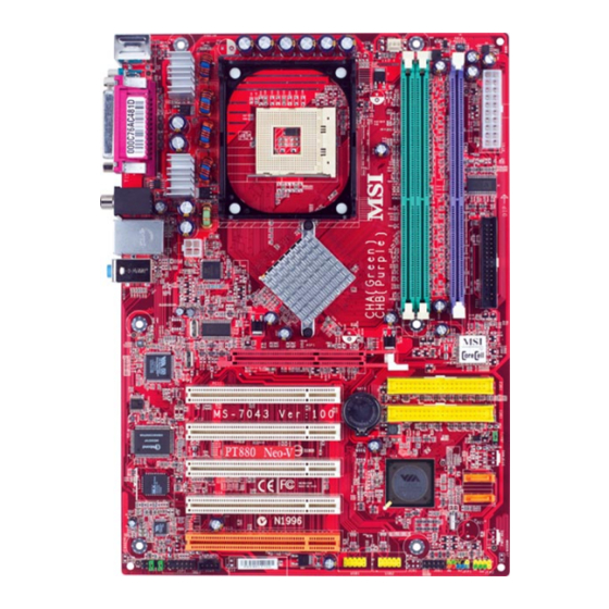
Page 9: Mainboard Layout
JPW1 Line-In Line-Out B: Mic VT6122 Gigabit LAN Winbond W83697HF BIOS VT1617 Audio Codec JCD1 JAUD1 JSP1 PT880 Neo-V (MS-7043 v1.X) ATX Mainboard CPUFA1 PT880 AGP1 PCI 1 BATT PCI 2 PCI 3 VT8237 PCI 4 PCI 5 JUSB1 JUSB2 - VIA ®... - Page 10 PCI 3 BIOS PCI 4 PCI 5 VT1617 Audio Codec JCD1 JAUD1 JSP1 PT8 Neo-V (MS-7043 v1.X) ATX Mainboard ® - VIA PT800 Northbridge ® - VIA VT6103L 10/100Mbps LAN - 2 Serial ATA connectors - 2 DDR DIMMs up to 2 GB...
- Page 11 Line-In Line-Out B: Mic VT6103L 10/100 LAN Winbond W83697HF BIOS VT1617 Audio Codec JCD1 JAUD1 JSP1 PX8 Neo-V (MS-7043 v1.X) ATX Mainboard - VIA CPUFA1 P4X533 AGP1 PCI 1 BATT PCI 2 PCI 3 VT8237 PCI 4 PCI 5 JUSB1 JUSB2 ®...
-
Page 12: Back Panel
Parallel Mouse Keyboard COMA Mouse/Keyboard Connector Pin5 Mouse/KBD Clock Pin6 NC Pin4 VCC Pin3 GND Pin1 Pin2 NC Mouse/KBD DATA Serial Port 1 2 3 4 5 6 7 8 9 USB Ports SIGNAL -Data +Data Back Panel SPDIF Out (Optional) USB Ports RJ-45 LAN Jack... -
Page 13: Chapter 2. Hardware Setup
Chapter 2. Hardware Setup Hardware Setup This chapter provides you with the information about hardware setup procedures. While doing the installation, be careful in holding the components and follow the installation procedures. For some components, if you install in the wrong orientation, the components will not work properly. -
Page 14: Central Processing Unit: Cpu
MS-7043 ATX Mainboard Central Processing Unit: CPU The mainboard supports Intel The mainboard uses a CPU socket called PGA478 for easy CPU installation. When you are installing the CPU, make sure the CPU has a heat sink and a cooling fan attached on the top to prevent overheating. -
Page 15: Cpu Installation Procedures For Socket 478
CPU Installation Procedures for Socket 478 1. Please turn off the power and unplug the power cord before installing the CPU. 2. Pull the lever sideways away from the socket. Make sure to raise the lever up to a 90-de- gree angle. -
Page 16: Installing The Cpu Fan
MS-7043 ATX Mainboard Installing the CPU Fan As processor technology pushes to faster speeds and higher performance, thermal management becomes increasingly important. To dissipate heat, you need to attach the CPU cooling fan and heatsink on top of the CPU. Follow the instructions below to install the Heatsink/Fan: 1. -
Page 17: Memory
Memory modules can be installed in any combination as follows: DIMM1 DIMM2 128MB~1GB 128MB~1GB 128MB~1GB 128MB~1GB 128MB~1GB 128MB~1GB 128MB~1GB 128MB~1GB Please refer to http://www.msi.com.tw/program/products/mainboard/ mbd/pro_mbd_trp_list.php for compatible DDR modules. Memory DIMM3 System Density 128MB~1GB 128MB~1GB 128MB~1GB 128MB~1GB 256MB~2GB 128MB~1GB 256MB~2GB... -
Page 18: Power Supply
MS-7043 ATX Mainboard The mainboard supports ATX power supply for the power system. Before inserting the power supply connector, always make sure that all components are installed properly to ensure that no damage will be caused. ATX 20-Pin Power Connector: ATX1 This connector allows you to connect to an ATX power supply. -
Page 19: Connectors
The mainboard provides connectors to connect to FDD, IDE HDD, case, USB Ports and CPU/System/Power Supply FAN. Floppy Disk Drive Connector: FDD1 The mainboard provides a standard floppy disk drive connector that supports 360K, 720K, 1.2M, 1.44M and 2.88M floppy disk types. S-Bracket (SPDIF) Connector: JSP1 (Optional) The connector allows you to connect a S-Bracket for Sony &... -
Page 20: Chassis Intrusion Switch Connector: Jci1 (Optional)
MS-7043 ATX Mainboard Chassis Intrusion Switch Connector: JCI1 (Optional) This connector is connected to a 2-pin chassis switch. If the chassis is opened, the switch will be short. The system will record this status and show a warning message on the screen. To clear the warning, you must enter the BIOS utility and clear the record. -
Page 21: Fan Power Connector: Cpufa1
System Hardware Monitor chipset onboard, you must use a specially designed fan with speed sensor to take advantage of the CPU fan control. MSI Reminds You... Always consult the vendors for proper CPU cooling fans. D-Bracket™ 2 Connector: JDB1 (Optional) The mainboard comes with a JDB1 connector for you to connect to D-Bracket™... -
Page 22: Hard Disk Connectors: Ide1 & Ide2
MS-7043 ATX Mainboard Hard Disk Connectors: IDE1 & IDE2 The mainboard has a 32-bit Enhanced PCI IDE and Ultra DMA 33/66/100/133 controller that provides PIO mode 0~4, Bus Master, and Ultra DMA 33/66/100/133 function. You can connect up to four hard disk drives, CD-ROM, 120MB Floppy and other devices. -
Page 23: Front Usb Connectors: Jusb1 & Jusb2
Front USB Connectors: JUSB1 & JUSB2 (Optional) The mainboard provides two USB 2.0 pin headers JUSB1 & JUSB2 (Optional) ® that are compliant with Intel increases data transfer rate up to a maximum throughput of 480Mbps, which is 40 times faster than USB 1.1, and is ideal for connecting high-speed USB interface peripherals such as USB HDD, digital cameras, MP3 players, printers, modems and the like. -
Page 24: Jumpers
Otherwise, the Line-Out connector on the back panel will not function. The motherboard provides the following jumpers for you to set the computer’s function. This section will explain how to change your motherboard’s function through the use of jumpers. -
Page 25: Slots
The mainboard provides one AGP slot and five 32-bit PCI bus slots. AGP (Accelerated Graphics Port) Slot The AGP slot allows you to insert the AGP graphics card. AGP is an interface specification designed for the throughput demands of 3D graphics. It introduces a 66MHz, 32-bit channel for the graphics controller to directly access main memory. -
Page 26: Chapter 3. Bios Setup
6th - 7th digit refers to the customer as MS = all standard customers. V1.0 refers to the BIOS version. 091096 refers to the date this BIOS was released For detailed BIOS setup information, please refer to our website at: http://www.msi.com.tw. BIOS Setup... -
Page 27: The Main Menu
MS-7043 ATX Mainboard The Main Menu Standard CMOS Features Use this menu for basic system configurations, such as time, date etc. Advanced BIOS Features ® Use this menu to setup the items of AMI special enhanced features. Advanced Chipset Features Use this menu to change the values in the chipset registers and optimize your system’s... -
Page 28: Frequency/Voltage Control
CPU while running programs, and to adjust the best CPU frequency automatically. When the motherboard detects that the CPU is running programs, it will speed up CPU automatically to make the program run smoothly and faster. When the CPU is temporarily suspending or staying in the low load balance, it will restore the default settings instead. - Page 29 CPU Ratio Selection This setting controls the multiplier that is used to determine the internal clock speed of the processor relative to the external or motherboard clock speed. CPU FSB Clock This setting shows the current CPU Front Side Bus clock frequency.
- Page 30 These two items configure the voltage of the North Bridge and the South Bridge for overclocking purposes. MSI Reminds You... The settings shown in different color in CPU Voltage, DDR Voltage, AGP Voltage, and North Bridge/South Bridge Voltage help to verify if your setting is proper for your system.
Need help?
Do you have a question about the MS-7043 and is the answer not in the manual?
Questions and answers