Table of Contents
Advertisement
Advertisement
Table of Contents

Related Manuals for MSI MS-7031


Summary of Contents for MSI MS-7031
- Page 1 RS350M MS-7031 (v1.X) M-ATX Mainboard G52-M7031X1...
-
Page 2: Fcc-B Radio Frequency Interference Statement
VOIR LA NOTICE D’INSTALLATION AVANT DE RACCORDER AU RESEAU. Micro-Star International MS-7031 This device complies with Part 15 of the FCC Rules. Operation is subject to the following two conditions: (1) this device may not cause harmful interference, and... -
Page 3: Copyright Notice
Copyright Notice The material in this document is the intellectual property of MICRO-STAR INTERNATIONAL. We take every care in the preparation of this document, but no guarantee is given as to the correctness of its contents. Our products are under continual improvement and we reserve the right to make changes without notice. -
Page 4: Safety Instructions
Alternatively, please try the following help resources for further guidance. Visit the MSI homepage & FAQ site for technical guide, BIOS updates, driver updates, and other information: http://www.msi.com.tw & http://www.msi. -
Page 5: Table Of Contents
Technical Support ......................iv Chapter 1. Getting Started ................... 1-1 Mainboard Specifications ..................1-2 Mainboard Layout ....................1-4 MSI Special Features ................... 1-5 Chapter 2. Hardware Setup ................. 2-1 Quick Components Guide ..................2-2 Central Processing Unit: CPU ................2-3 Example of CPU Core Speed Derivation Procedure ........ - Page 6 Fan Power Connectors: CPUFAN1/SYSFAN1 .......... 2-14 Hard Disk Connectors: IDE1 & IDE2 ............2-15 CD-In Connector: JCD1 ................2-16 SPDIF-Out Connector: JSPD1 (Optional) ........... 2-16 Front USB Connectors: JUSB1 / JUSB2 ............ 2-16 Front Panel Connector: JFP1 ..............2-17 Front Panel Audio Connector: JAUD1 ............2-17 Serial ATA Connectors controlled by ATI IXP 300: SATA1, SATA2 ..
- Page 7 Playing KaraOK ....................4-10 Chapter 5. Introduction to ATi IXP 300 SATA RAID .......... 5-1 Introduction ......................5-2 BIOS Configuration ....................5-3 Installing Software ....................5-5...
-
Page 8: Chapter 1. Getting Started
Getting Started Getting Started Thank you for purchasing RS350M Series (MS-7031) v1.X Micro ATX mainboard. The RS350M Series is based on ATI ® Radeon ® 9100 IGP Pro & ATI IXP 300 chipsets and provides 8 USB 2.0 ports for high-speed data transmission. With all these special designs, the RS350M Series delivers a high performance and pro- fessional desktop platform solution. -
Page 9: Mainboard Specifications
Mainboard Specifications Socket 478 for P4 processors (Northwood/Prescott) at 400/533/800 MHz Supports up to 3.4GHz. Hyper-Threading CPU. (For the latest information about CPU, please visit http://www.msi.com.tw/program/ products/mainboard/mbd/pro_mbd_cpu_support.php) Chipset ATI Radeon 9100 IGP Pro - Supports AGP 8x/4x at 0.8V (AGP 3.0) or 4x at 1.5V... - Page 10 Micro-ATX Form Factor: 24.4 cm (L) x 24.4 cm (W). Mounting 8 mounting holes. Others Live BIOS/Live Driver Update PC2001 Compliant Suspends to RAM/Disk MSI Reminds You... The Windows 98 & Windows ME operating systems are not sup- ported by this mainboard. 1 - 3...
-
Page 11: Mainboard Layout
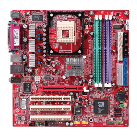
MS-7031 Micro ATX Mainboard Mainboard Layout T: mouse B: keyboard Winbond W83627THF CPUFAN1 JTV1 (Optional) Radeon 9100 IGP Pro Line-In Line-Out B:Mic JPW1 AGP Slot PCI Slot 1 JCMOS1 PCI Slot 2 SYSFAN1 IXP300 BIOS SATA1 PCI Slot 3 SATA2... -
Page 12: Msi Special Features
BIOS/VGA Driver/OSD/Utility online so that you don’t need to search for the correct BIOS/driver version throughout the whole Web site. To use the function, you need to install the “MSI Live Update 3” application. After the installation, the “MSI Live Update 3”... -
Page 13: Core Center
MS-7031 Micro ATX Mainboard Core Center CoreCenter is just like your PC doctor that can detect, view and adjust the PC hardware and system status during real time operation. In the left side it shows the current system status including the Vcore, 3.3V, +5V and 12V. - Page 14 Getting Started Left-wing: Current system status In the left sub-menu, you can configure the settings of FSB, Vcore, Memory Voltage and AGP Voltage by clicking the radio button next to each item and make it available (the radio button will be lighted as yellow when selected), use the “+” and “-” buttons to adjust, then click “OK”...
-
Page 15: Chapter 2. Hardware Setup
Hardware Setup Chapter 2. Hardware Setup Hardware Setup This chapter tells you how to install the CPU, memory modules, and expansion cards, as well as how to setup the jumpers on the mainboard. Also, it provides the instructions on connecting the peripheral devices, such as the mouse, keyboard, etc. -
Page 16: Quick Components Guide
MS-7031 Micro ATX Mainboard Quick Components Guide CPU_FAN1, p.2-14 JTV1, p.2-20 DDR DIMMs, p.2-6 CPU, p.2-3 JPW1, p.2-8 IDE2, p.2-15 FDD1, p.2-14 Back Panel I/O, p.2-9 IDE1, p.2-15 AGP slot, ATX1, p.2-8 p.2-22 PCI slots, SYSFAN1, p.2-14 p.2-22 JCMOS1, p.2-21 SATA1, SATA2 p.2-18... -
Page 17: Central Processing Unit: Cpu
Memory Speed/CPU FSB Support Matrix Memory DDR 266 DDR 333 DDR 400 400 MHz 533 MHz 800 MHz MSI Reminds You... For the tested & compatible memory modules, please go to MSI global website (http://www.msi.com.tw) for the updated details. 2 - 3... -
Page 18: Cpu Installation Procedures For Socket 478
MS-7031 Micro ATX Mainboard CPU Installation Procedures for Socket 478 Please turn off the power and unplug the power cord before Open Lever installing the CPU. Sliding 90 degree Plate Pull the lever sideways away from the socket. Make sure to raise the lever up to a 90-de- gree angle. -
Page 19: Installing The Cpu Fan
5. Connect the fan power cable from the mounted fan to the 3-pin fan power connector on the board. MSI Reminds You... If your Intel Pentium 4 proces- fan power cable sor supports 3.0GHz (and up), please be sure to use a... -
Page 20: Memory
However, the same type and density memory modules are necessary while using dual-channel DDR, or instability may happen. MSI Reminds You... For the tested & compatible memory modules, please go to MSI global website (http://www.msi.com.tw) for the updated details. 2 - 6... -
Page 21: Installing Ddr Modules
128MB~1GB 128MB~1GB 128MB~1GB 512MB~4GB MSI Reminds You... 1. Dual-channel DDR works ONLY in the 3 combinations listed in the table above. 2. Due to the South Bridge resource deployment, the system density will only be detected up to 3+ GB (not to full 4GB) when each DIMM is installed with an 1GB memory module. -
Page 22: Power Supply
MS-7031 Micro ATX Mainboard Power Supply The mainboard supports ATX power supply for the power system. Before inserting the power supply connector, always make sure that all components are installed properly to ensure that no damage will be caused. ATX 20-Pin Power Connector: ATX1 This connector allows you to connect to an ATX power supply. -
Page 23: Back Panel
Hardware Setup Back Panel The back panel provides the following connectors: (Optional) Parallel (Optional) Mouse 1394 COM 1 L-in Keyboard (Optional) L-out Mouse Connector The mainboard provides a standard PS/2 mouse mini DIN connector for at- ® taching a PS/2 mouse. -
Page 24: Lan Jack: 10/100 Lan (8100C) /Giga-Bit Lan (8110Sb) (Optional)
MS-7031 Micro ATX Mainboard RJ-45 LAN Jack: 10/100 LAN (8100C) /Giga-bit LAN (8110SB) (Optional) The mainboard provides two standard RJ-45 jacks for connection to Local Area Network (LAN). Giga-bit LAN enables data to be transferred at 1000, 100 or 10Mbps. You can connect a network cable to either LAN jack. -
Page 25: Ieee1394 Port (Optional)
Hardware Setup IEEE1394 Port (Optional) The mainboard provides one standard IEEE1394 port. The stand- ard IEEE1394 port connects to IEEE1394 devices without exter- nal power. The IEEE1394 high-speed serial bus complements USB by providing enhanced PC connectivity for a wide range of devices, including consumer electronics audio/video (A/V) appliances, storage peripherals, other PCs, and portable devices. -
Page 26: Usb Connectors
MS-7031 Micro ATX Mainboard USB Connectors The mainboard provides a UHCI (Universal Host Controller Interface) Universal Serial Bus root for attaching USB devices such as keyboard, mouse or other USB- compatible devices. You can plug the USB device directly into the connector. -
Page 27: Parallel Port Connector: Lpt1
Hardware Setup Parallel Port Connector: LPT1 The mainboard provides a 25-pin female centronic connector as LPT. A parallel port is a standard printer port that supports Enhanced Parallel Port (EPP) and Extended Capabilities Parallel Port (ECP) mode. Pin Definition SIGNAL DESCRIPTION STROBE Strobe... -
Page 28: Connectors
MS-7031 Micro ATX Mainboard Connectors The mainboard provides connectors to connect to FDD, IDE HDD, case, modem, LAN, USB Ports and CPU/System/Power Supply FAN. Floppy Disk Drive Connector: FDD1 The mainboard provides a standard floppy disk drive connector that supports 360K, 720K, 1.2M, 1.44M and 2.88M floppy disk types. -
Page 29: Hard Disk Connectors: Ide1 & Ide2
IDE2 (Secondary IDE Connector) IDE2 can also connect a Master and a Slave drive. MSI Reminds You... If you install two hard disks on cable, you must configure the second drive to Slave mode by setting its jumper. Refer to the hard disk documentation supplied by hard disk vendors for jumper setting instructions. -
Page 30: Cd-In Connector: Jcd1
MS-7031 Micro ATX Mainboard CD-In Connector: JCD1 The connector is for CD-ROM audio connector. SPDIF-Out Connector: JSPD1 (Optional) This connector is used to connect SPDIF (Sony & Philips Digital Interconnect Format) interface for digital audio transmission. JCD1 SPDIF JSPD1 Connected to JSPD1... -
Page 31: Front Panel Connector: Jfp1
Left channel audio signal to front panel AUD_RET_L Left channel audio signal return from front panel MSI Reminds You... If you don’t want to connect to the front audio header, pins 5 & 6, 9 & 10 have to be jumpered in order to have signal output directed to the rear audio ports. -
Page 32: Serial Ata Connectors Controlled By Ati Ixp 300: Sata1, Sata2
MS-7031 Micro ATX Mainboard Serial ATA Connectors controlled by ATI IXP 300: SATA1, SATA2 The Southbridge of this mainboard is ATI IXP 300 which supports two serial connectors SATA1 & SATA2. SATA1 & SATA2 are dual high-speed Serial ATA interface ports. Each supports generation serial ATA data rates of 150 MB/s. -
Page 33: Ieee 1394 Connector: J1394_1 (Optional)
Hardware Setup IEEE 1394 Connector: J1394_1 (Optional) The mainboard provides one 1394 pin header that allows you to connect optional IEEE 1394 bracket. Pin Definition SIGNAL SIGNAL TPA+ TPA- Ground Ground J1394_1 TPB+ TPB- Cable power Cable power Key (no pin) Ground How to attach the IEEE 1394 Port: Connected to J1394_1... -
Page 34: Tv-Out Connector: Jtv1 (Optional)
MS-7031 Micro ATX Mainboard TV-Out Connector: JTV1 (Optional) The mainboard optionally provides a TV-Out connector for you to attach a TV- Out bracket. The TV-Out bracket offers two types of TV-Out connectors: S-Video and RCA Composite connector. Select the appropriate one to connect to the televi- sion and the television will be able to display the PC’s information. -
Page 35: Jumpers
JCMOS1 Keep Data Clear Data MSI Reminds You... You can clear CMOS by shorting 2-3 & 5-6 pin while the system is off (always turn off the ATX power supply or unplug the power cord). Then return to 1-2 & 4-5 pin position. Avoid clearing the CMOS while the system is on;... -
Page 36: Slots
MS-7031 Micro ATX Mainboard Slots The motherboard provides one AGP slot and three 32-bit PCI bus slots. AGP (Accelerated Graphics Port) Slot The AGP slot allows you to insert the AGP graphics card. AGP is an interface specification designed for the throughput demands of 3D graphics. It introduces a 66MHz, 32-bit channel for the graphics controller to directly access main memory. -
Page 37: Chapter 3. Bios Setup
An error message appears on the screen during system boot up, and requests you to run SETUP. You want to change the default settings for customized features. MSI Reminds You... 1. The items under each BIOS category described in this chapter are under continuous update for better system performance. -
Page 38: Entering Setup
MS-7031 Micro ATX Mainboard Entering Setup Power on the computer and the system will start POST (Power On Self Test) process. When the message below appears on the screen, press <DEL> key to enter Setup. P r e s s... -
Page 39: The Main Menu
BIOS Setup The Main Menu ® Once you enter Phoenix-Award BIOS CMOS Setup Utility, the Main Menu will appear on the screen. The Main Menu allows you to select from the on-screen setup functions and two exit choices. Use arrow keys to select among the items and press <Enter>... - Page 40 MS-7031 Micro ATX Mainboard Load Fail-Safe Defaults Use this menu to load the default values set by the BIOS vendor for stable system performance. Load Optimized Defaults Use this menu to load the default values set by the mainboard manufacturer specifi- cally for optimal performance of the mainboard.
-
Page 41: Standard Cmos Features
BIOS Setup Standard CMOS Features The items in Standard CMOS Features Menu includes some basic setup items. Use the arrow keys to highlight the item and then use the <PgUp> or <PgDn> keys to select the value you want in each item. Date This allows you to set the system to the date that you want (usually the current date). - Page 42 MS-7031 Micro ATX Mainboard Drive A: This item allows you to set the type of floppy drives installed. Available options: [None], [360K, 5.25 in.], [1.2M, 5.25 in.], [720K, 3.5 in.], [1.44M, 3.5 in.], [2.88M, 3.5 in.]. Video The setting controls the type of video adapter used for the primary monitor of the system.
-
Page 43: Advanced Bios Features
In this way, the system performance is highly improved. If you disable the function, the processor will use only one core to execute the instructions. Settings: [Disabled] and [Enabled]. MSI Reminds You... Enabling the functionality of Hyper-Threading Technology for your computer system requires ALL of the following platform Components: ®... - Page 44 MS-7031 Micro ATX Mainboard Full Screen LOGO Show This item enables you to show the company logo on the bootup screen. Settings are: [Enabled] Shows a still image (logo) on the full screen at boot. [Disabled] Shows the POST messages at boot.
-
Page 45: Advanced Chipset Features
BIOS Setup Advanced Chipset Features MSI Reminds You... Change these settings only if you are familiar with the chipset. DRAM Clock By Selects whether DRAM clock is controlled by the SPD (Serial Presence Detect) EEPROM on the DRAM module. Setting to [By SPD] enables the following fields auto- matically to be determined by BIOS based on the configurations on the SPD. - Page 46 MS-7031 Micro ATX Mainboard TRCD When DRAM is refreshed, both rows and columns are addressed separately. This setup item allows you to determine the timing of the transition from RAS (row address strobe) to CAS (column address strobe). The less the clock cycles, the faster the DRAM performance.
- Page 47 BIOS Setup TV Standard Select the TV standard which is used as the video signal format of your TV if you have connected a TV to the system. Three TV standards are available for the field: [NTSC] NTSC format which is used in United States. [PAL] PAL format.
-
Page 48: Integrated Peripherals
MS-7031 Micro ATX Mainboard Integrated Peripherals USB Controller Select [Enabled] if your system contains a Universal Serial Bus (USB) controller and you have USB peripherals. Setting options: [Disabled], [Enabled]. USB 2.0 Controller Set to [Enabled] if you need to use any USB 2.0 device in the operating system that does not support or have any USB 2.0 driver installed, such as DOS and SCO Unix. - Page 49 BIOS Setup IDE Device Configuration Press <Enter> to enter the sub-menu and the following screen appears: On-Chip IDE Channel0/1 The integrated peripheral controller contains an IDE interface with support for two IDE channels. Choose [Enabled] to activate each channel separately. Setting options: [Enabled], [Disabled].
- Page 50 MS-7031 Micro ATX Mainboard SATA Device Configuration Press <Enter> to enter the sub-menu and the following screen appears: Onboard Serial ATA This item is used to enable/disable the onboard Serial ATA controller. Setting options: [Enabled], [Disabled]. Serial ATA Mode This item is used to set the SATA configuration. Select [IDE] if you want to have SATA as IDE function, and select [RAID] to use SATA as RAID function.
- Page 51 BIOS Setup Parallel Port Mode SPP : Standard Parallel Port EPP : Enhanced Parallel Port ECP : Extended Capability Port ECP + EPP: Extended Capability Port + Enhanced Parallel Port Normal SPP/EPP/ECP/ECP+EPP To operate the onboard parallel port as Standard Parallel Port only, choose [SPP]. To operate the onboard parallel port in the EPP mode simultaneously, choose [EPP].
-
Page 52: Power Management Setup
MS-7031 Micro ATX Mainboard Power Management Setup MSI Reminds You... S3-related functions described in this section are available only when your BIOS supports S3 sleep mode. ACPI Function This item is to activate the ACPI (Advanced Configuration and Power Management Interface) Function. - Page 53 BIOS Setup Wake Up Event Setup Press <Enter> and the following sub-menu appears. Resume by PCI (PME #) This controls how and whether the system can be powered on by the devices installed on PCI slots. Setting options: [Disabled], [Enabled]. POWER ON Function This controls how the PS/2 mouse or keyboard can power on the system.
-
Page 54: Pnp/Pci Configurations
MS-7031 Micro ATX Mainboard PNP/PCI Configurations This section describes configuring the PCI bus system and PnP (Plug & Play) feature. PCI, or Peripheral Component Interconnect, is a system which allows I/O devices to operate at speeds nearing the speed the CPU itself uses when communi- cating with its special components. - Page 55 BIOS Setup Assign IRQ For VGA/USB Set to [Enabled] allows BIOS to assign an IRQ to VGA card/USB device. Choose [Disabled] if you want to release the IRQ. Setting options: [Enabled], [Disabled]. PCI Latency Timer (CLK) This item controls how long each PCI device can hold the bus before another takes over.
-
Page 56: Pc Health Status
MS-7031 Micro ATX Mainboard PC Health Status This section shows the status of your CPU, fan, overall system status, etc. Monitor function is available only if there is hardware monitoring mechanism onboard. CPU Warning Temperature This item is used to specify a thermal limit for CPU. If CPU temperature reaches the specified limit, the system will issue a warning which allows you to prevent the CPU overheat problem. -
Page 57: Frequency/Voltage Control
BIOS Setup Frequency/Voltage Control Use this menu to specify your settings for frequency/voltage control. Current CPU FSB Clock/DRAM Clock These two items show the current clocks of CPU/DRAM. Read-only. CPU Clock Ratio This setting controls the multiplier that is used to determine the internal clock speed of the processor relative to the external or motherboard clock speed. - Page 58 MS-7031 Micro ATX Mainboard Spectrum if you are overclocking because even a slight jitter can introduce a tempo- rary boost in clock speed which may just cause your overclocked processor to lock up. Options: [Disabled], [Enabled]. Adjust CPU FSB Clock This item specifies the clock frequency of CPU host bus (FSB), AGP (3V66) and PCI bus.
-
Page 59: Load Fail-Safe/Optimized Defaults
BIOS Setup Load Fail-Safe/Optimized Defaults The two options on the main menu allow users to restore all of the BIOS settings to the default Fail-Safe or Optimized values. The Optimized Defaults are the default values set by the mainboard manufacturer specifically for optimal performance of the mainboard. -
Page 60: Bios Setting Password
MS-7031 Micro ATX Mainboard BIOS Setting Password When you select this function, a message as below will appear on the screen: Type the password, up to eight characters in length, and press <Enter>. The pass- word typed now will replace any previously set password from CMOS memory. You will be prompted to confirm the password. -
Page 61: Chapter 4. Introduction To Alc655 Audio Codec
Introduction to ALC655 Audio Codec Chapter 4. Introduction to DigiCell Chapter 2. Hardware Setup Introduction to ALC655 Audio Codec The motherboard is equipped with Realtek ALC655 chip, which pro- vides support for 6-channel audio output, including 2 Front, 2 Rear, 1 Center and 1 Subwoofer channel. -
Page 62: Installing The Audio Driver
MS-7031 Micro ATX Mainboard Installing the Audio Driver You need to install the driver for Realtek ALC655 chip to function properly before you can get access to 4-/6-channel audio operations. Follow the procedures described below to install the drivers for different operating systems. - Page 63 Introduction to ALC655 Audio Codec 3. Click Next to start installing files into the system. 4. Click Finish to restart the system. Select this option 4 - 3...
-
Page 64: Using 2-, 4- Or 6-Channel Audio Function
MS-7031 Micro ATX Mainboard Using 2-, 4- or 6-Channel Audio Function After installing the audio driver, you are able to use the 2-/4-/6-channel audio feature now. To enable 2-, 4- or 6-channel audio operation, first connect 2, 4 or 6 speakers to the appropriate audio connectors, and then select 2-, 4- or 6-channel audio setting in the software utility. - Page 65 Introduction to ALC655 Audio Codec 4 - 5...
- Page 66 MS-7031 Micro ATX Mainboard Connecting the Speakers When you have set the Multi-Channel Audio Function mode properly in the software utility, connect your speakers to the correct phone jacks in accordance with the setting in software utility. 2-Channel Mode for Stereo-Speaker Output Refer to the following diagram and caption for the function of each phone jack on the back panel when 2-Channel Mode is selected.
- Page 67 Line Out func- tion when 6-Channel Mode for 6-Speaker Output is selected. MSI Reminds You... If the Center and Subwoofer speaker exchange their audio channels when you play video or music on the computer, a converter may be required to exchange center and subwoofer audio signals.
-
Page 68: Testing The Connected Speakers
MS-7031 Micro ATX Mainboard Testing the Connected Speakers To ensure that 4- or 6-channel audio operation works properly, you may need to test each connected speaker to make sure every speaker work properly. If any speaker fails to make sound, then check whether the cable is inserted firmly to the connector or replace the bad speakers with good ones. - Page 69 Introduction to ALC655 Audio Codec 4. While you are testing the speakers in 6-Channel Mode, if the sound coming from the center speaker and subwoofer is swapped, you should select Swap Center/ Subwoofer Output to readjust these two channels. Select this function 4 - 9...
-
Page 70: Playing Karaok
MS-7031 Micro ATX Mainboard Playing KaraOK The KaraOK function will automatically remove human voice (lyrics) and leave melody for you to sing the song. Note that this function applies only for 2-channel audio operation. Playing KaraOK 1. Click the audio icon from the window tray at the lower-right corner of the screen. -
Page 71: Chapter 5. Introduction To Ati Ixp 300 Sata Raid
- UDMA up to 150MB/Sec - All UDMA and PIO modes - Up to 2 SATA devices - ACPI and ATA/ATAPI6 MSI Reminds You... All the information/volumes listed in your system might differ from the illustrations in this appendix. 5 - 1... -
Page 72: Introduction
MS-7031 Micro ATX Mainboard Introduction RAID - Redundant Array of Independent Disks RAID technology manages multiple disk drives to enhance I/O performance and provide redundancy in order to withstand the failure of any individual member, without loss of data. SATA RAID provides two RAID Set types, Striping (RAID 0) and Mirroring (RAID 1). -
Page 73: Bios Configuration
Using the RAID Configuration Utility 1. Creating, Deleting and Rebuilding RAID Sets: The RAID Utility menu screen will be displayed, shown as following. MSI Reminds You... The “Driver Model” and “Size” in the following example might be different from your system. - Page 74 MS-7031 Micro ATX Mainboard (2) Delete RAID Sets 1. Select the Delete RAID Set in the main menu, and select the desire set and press <Enter>. 2. Press Y when asked “Are You Sure?” 3. The drive will be returned to the original status which the RAID Set can be created.
-
Page 75: Installing Software
You may make the Serial ATA RAID driver by yourself by following the instruction below. 1. Insert the MSI CD into the CD-ROM drive. 2. Ignore the Setup screen and use “Explorer” to browse the CD.
Need help?
Do you have a question about the MS-7031 and is the answer not in the manual?
Questions and answers