Table of Contents
Advertisement
Available languages
Available languages
FCC-B Radio Frequency Interference Statement
This equipment has been tested and found to comply with the limits for a class B digital device, pursuant to
part 15 of the FCC rules. These limits are designed to provide reasonable protection against harmful
interference when the equipment is operated in a commercial environment. This equipment generates, uses
and can radiate radio frequency energy and, if not installed and used in accordance with the instruction
manual, may cause harmful interference to radio communications. Operation of this equipment in a
residential area is likely to cause harmful interference, in which case the user will be required to correct the
interference at his own expense.
Notice 1
The changes or modifications not expressly approved by the party responsible for compliance could void the
user's authority to operate the equipment.
Notice 2
Shielded interface cables and A.C. power cord, if any, must be used in order to comply with the emission
limits.
VOIR LA NOTICE D'NSTALLATION AVANT DE RACCORDER AU RESEAU.
This device complies with Part 15 of the FCC Rules. Operation is subject to the following two conditions:
(1) this device may not cause harmful interference, and
(2) this device must accept any interference received, including interference that may cause undesired
operation
Micro-Star International
MS-7071
G52-M7071X1
i
Advertisement
Table of Contents

Related Manuals for MSI MS-7071


Summary of Contents for MSI MS-7071
- Page 1 This device complies with Part 15 of the FCC Rules. Operation is subject to the following two conditions: (1) this device may not cause harmful interference, and (2) this device must accept any interference received, including interference that may cause undesired operation Micro-Star International MS-7071 G52-M7071X1...
- Page 2 Copyright Notice The material in this document is the intellectual property of MICRO-STAR INTERNATIONAL. We take every care in the preparation of this document, but no guarantee is given as to the correctness of its contents. Our products are under continual improvement and we reserve the right to make changes without notice. Trademarks All trademarks are the properties of their respective owners.
- Page 3 Safety Instructions 1. Always read the safety instructions carefully. 2. Keep this User Manual for future reference. 3. Keep this equipment away from humidity. 4. Lay this equipment on a reliable flat surface before setting it up. 5. The openings on the enclosure are for air convection hence protects the equipment from overheating. Do not cover the openings.
- Page 4 Table of Contents English...1 Français...17 Deutsch...31 简体中文 ...49 繁體中文 ...63 日本語...77...
-
Page 5: Specifications
Introduction Thank you for purchasing the PM8M2-V Series (MS-7071 v1.X) M-ATX mainboard. This mainboard is based on VIA P4M800 and VT8237R chipsets for optimal system efficiency. Designed to fit the advanced Intel Pentium 4 Prescott processor, the PM8M2-V Series mainboard delivers a high performance and professional desktop platform solution. - Page 6 Onboard IDE An IDE controller integrated in the VIA VT8237R chipset providing IDE HDD/CD-ROM with PIO, Bus Master and Ultra DMA 66/100/133 operation modes Can connect up to four IDE devices On-Board Peripherals l On-Board Peripherals include: 1 floppy port supports 2 FDD with 360K, 720K, 1.2M, 1.44M and 2.88Mbytes 1 serial port (COM A) 1 parallel port supports SPP/EPP/ECP mode 8 USB 2.0 ports (Rear x4 / Front x4)
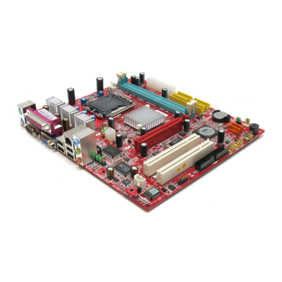
- Page 7 USB ports Top: LAN Jack Bottom: USB ports Line-In Line-Out Codec JSP1 JAUDIO1 COM2 P4M800 (645BGA) AGP Slot PCI Slot 1 PCI Slot 2 MS-7071 v1.X Micro-ATX Mainboard IDE 2 IDE 1 SATA2 SATA1 BATT JFP2 JUSB1 JUSB2 JBAT2 JFP1...
-
Page 8: Rear Panel
If you do not find the heat sink and cooling fan, contact your dealer to purchase and install them before turning on the computer. (For the latest information about CPU, please visit our Web site at http://www.msi.com.tw/program/products/mainboard/mbd/pro_mbd_cpu_support.php Example of CPU Core Speed Derivation Procedure CPU Clock... -
Page 9: Lga775 Cpu & Cooler Installation
MSI Reminds You... Overheating Overheating will seriously damage the CPU and system, always make sure the cooling fan can work properly to protect the CPU from overheating. Replacing the CPU While replacing the CPU, always turn off the ATX power supply or unplug the power supply’ s power cord from grounded outlet first to ensure the safety of CPU. -
Page 10: Memory
2GB. Install at least one DIMM module on the slots. Each DIMM slot supports up to a maximum size of 1GB. You can install either single- or double-sided modules to meet your own needs. Please refer to http://www.msi.com.tw/program/products/mainboard/mbd/pro_mbd_trp_list.php for compatible DDR modules. Installing DDR Modules 1. -
Page 11: Power Supply
166 MHz 200MHz For the updated supporting memory modules, please visit our Web site at http://www.msi.com.tw/program/products/mainboard/mbd/pro_mbd_trp_list.php Power Supply The mainboard supports ATX power supply for the power system. Before inserting the power supply connector, always make sure that all components are installed properly to ensure that no damage will be caused. -
Page 12: Serial Ata Connectors
Slave drive. You must configure second hard drive to Slave mode by setting the jumper accordingly. IDE2 can also connect a Master and a Slave drive. MSI Reminds You... If you install two hard disks on cable, you must configure the second drive to Slave mode by setting its jumper. -
Page 13: Front Panel/Front Usb Connectors
USB 1.1, and is ideal for connecting high-speed USB interface peripherals such as USB HDD, digital cameras, MP3 players, printers, modems and the like. MSI Reminds You... Note that the pins of VCC and GND must be connected correctly or it may cause some damage. Serial Port Connector: COM2 The mainboard offers one serial port connector without housing. - Page 14 Front Panel I/O Connectivity Design Guide. MSI Reminds You... If you do not want to connect to the front audio header, pins 5 & 6, 9 & 10 have to be jumpered in order to have signal output directed to the rear audio ports.
-
Page 15: Pci Interrupt Request Routing
The CNR slot allows you to insert the CNR expansion card. CNR is a specially designed audio, or modem riser card for ATX family motherboards. Its main processing is done through software and controlled by the motherboard’ s chipset. PCI Interrupt Request Routing The IRQ, acronym of interrupt request line and pronounced I-R-Q, are hardware lines over which devices can send interrupt signals to the microprocessor. - Page 16 BIOS Setup Power on the computer and the system will start POST (Power On Self Test) process. When the message below appears on the screen, press <DEL> key to enter Setup. DEL: Setup If the message disappears before you respond and you still wish to enter Setup, restart the system by turning it OFF and On or pressing the RESET button.
- Page 17 This entry appears if your system supports PnP/PCI. H/W Monitor This entry shows information of your CPU, fan and overall system status. Frequency/Voltage Control Use this menu to specify your settings for CPU/AGP frequency/voltage control and overclocking. Load Optimized Defaults Use this menu to load the BIOS values for the best system performance, but the system stability may be affected.
- Page 18 Adjust CPU Ratio This setting controls the multiplier that is used to determine the internal clock speed of the processor relative to the external or motherboard clock speed. Adjust CPU/AGP/PCI Frequency This setting allows you to select the clock frequency of CPU/AGP/PCI.
- Page 19 Spread Spectrum When the motherboard’ s clock generator pulses, the extreme values (spikes) of the pulses create EMI (Electromagnetic Interference). The Spread Spectrum function reduces the EMI generated by modulating the pulses so that the spikes of the pulses are reduced to flatter curves.
-
Page 20: Load Optimized Defaults
Load Optimized Defaults You can load the optimized values provided by the mainboard manufacturer for the stable performance. For the complete BIOS introduction and setup, please visit MSI website at http://www.msi.com.tw. - Page 21 Introduction Félicitations, vous venez d’ a cquérir une carte mère M -ATX PM8M2-V Series (MS-7071 v1.X). Cette carte mère est basée sur les Chipsets VIA P4M800 et VT8237R offrant un système très performant. La carte fonctionne avec les processeurs Intel Pentium 4 Prescott, la PM8M2-V Series et offre une solution adaptée tant aux professionnels qu’...
- Page 22 opératoires IDE HDD/CD-ROM avec PIO, Bus Master et Ultra DMA 66/100/133 Possibilité de connecter jusqu’ à quatre matéri els IDE Périphériques Intégrés l Périphériques intégrés inclus: 1 port floppy supportant 2 FDD avec 360K, 720K, 1.2M, 1.44M et 2.88Mbytes 1 port série (COM A) 1 port parallèle supportant les modes SPP/EPP/ECP 8 ports USB 2.0 (Arrière x4 / Avant x4) Ports Audio verticaux...
- Page 23 Top: LAN Jack Bottom: USB ports Line-In Line-Out Codec JSP1 JAUDIO1 COM2 P4M800 (645BGA) AGP Slot PCI Slot 1 PCI Slot 2 Carte Mère Micro ATX MS-7071 v1.X IDE 2 IDE 1 SATA2 SATA1 BATT JFP2 JUSB1 JUSB2 JBAT2 JFP1...
- Page 24 Procédure de dérivation du CPU Core Speed Horloge CPU Multiplicateur Alors Vitesse CPU MSI Vous Rappelle... Surchauffe Une surchauffe endommagera sérieusement le CPU et le système. Soyez toujours sur du bon fonctionnement des ventilateurs et radiateurs pour protéger le CPU d’ une surchauffe. Overclocking Cette carte mère a été...
- Page 25 CPU pour aligner la broche n°1 (triangle jaune) avec le coin en bas à gauche du socket.. Prendre le CPU Clip bleu de MSI et le faire tourner afin qu’ i l s’ a ligne avec le socket. Il faut ensuite retirer la protection qui se trouve sur le socket de la carte mère.
- Page 26 MSI Vous Rappelle... Vérifier la connexion du ventilateur de CPU avant de démarre le PC. Vérifier les informations dans le BIOS PC Health Status du H/W Monitor au sujet de la température du CPU. Ne pas toucher les broches du CPU pour éviter de les endommager.
- Page 27 166 MHz 200MHz (Pour les dernières mises à jours de mémoire supportées, merci de visiter http://www.msi.com.tw/program/products/mainboard/mbd/pro_mbd_trp_list.php ) Alimentation La carte mère supporte les alimentations ATX. Avant de brancher le connecteur d’ a limentation, Il faut toujours vous assurer que tous les composants sont bien installés afin de ne pas les endommager.
- Page 28 MSI Vous Rappelle... Si vous voulez installer deux disques durs, vous devez configurer le second en Esclave en configurant le cavalier. Se référer à la documentation du disque dur pour les instructions.
- Page 29 à 480 Mbps, ce qui est 40 fois plus rapide que l’ USB 1.1. Idéal pour connecter des périphériques gourmand en bande passante (appareil photo numérique, caméra numérique etc) MSI Vous Rappelle... A noter que les broches VCC et GND doivent être correctement connecter afin d’ éviter tout endommagement.
- Page 30 (Cavalier Clear CMOS) pour effacer les données. Suivez les instructions de l’ i mage pour effacer les données. MSI Vous Rappelle... Vous pouvez effacer les données en positionnant le cavalier sur les broches 2-3 quand le PC n’ est pas allumé. Puis il faut remettre le cavalier en position 1-2. Ne surtout pas effacer les données (Position 2-3) lorsque le PC est en fonction, cela endommagera la carte mère.
- Page 31 Setup du BIOS Lorsque le PC démarre le processus de POST (Power On Self Test) se met en route. Quand le message ci-dessous apparaî t, appuyer sur <DEL> pour accéder au Setup. DEL: Setup Si le message disparaî t avant que n’ a yez appuyé sur la touche, redémarrez le PC à l’ a ide du bouton RESET.
- Page 32 PNP/PCI Configurations Apparaît si votre système supporte PNP/PCI. H/W Monitor Cette entrée montre le statut de votre CPU, ventilateur. Frequency/Voltage Control Utiliser ce menu pour configurer vos paramètres de pour le contrôle de la fréquence et du voltage. Load BIOS Defaults Utiliser ce menu pour charger les paramètres par défaut du BIOS.
- Page 33 Frequency/Voltage Control Les éléments de ce menu contiennent des paramètres importants concernant CPU, AGP, DRAM et l’ o verclocking . MSI Vous rappelle... Vous pouvez changer ces paramètres uniquement si vous êtes familiarisés avec le chipset. Current FSB Frequency Montre la fréquence d’ h orloge du front side bus. (à lire uniquement) Adjust CPU Ratio Cet élément permet de modifier le ration CPU.
- Page 34 é viter tout problème. Les options : [Disabled], [Enabled]. Load Optimized Defaults Vous pouvez charger les paramètres par défaut procurés par le constructeur de la carte mère pour une performance stable. Pour des informations complètes sur le BIOS, vous pouvez visiter : http://www.msi.com.tw.
- Page 35 Einleitung Danke, dass Sie sich für das PM8M2-V Series (MS-7071 v1.X) M-ATX Mainboard entschieden haben. Dieses Mainboard basiert auf den VIA P4M800 und VT8237R Chipsätzen und ermöglicht so ein optimales und effizientes System. Entworfen, um den fortschrittlichen Intel Pentium 4 Prescott Prozessor aufzunehmen, stellt das PM8M2-V Series die ideale Lösung zum Aufbau eines professionellen Hochleistungsdesktopsystems dar.
- Page 36 Onboard IDE Der im VIA VT8237R Chipsatz enthaltene IDE Kontroller bietet für den Festplatten- und CD-ROM-Zugriff PIO, Bus Mastering und Betrieb mit Ultra DMA 66/100/133 Bis zu vier IDE Geräte anschließbar. Peripherieanschlüsse onboard l hierzu gehören: 1 Anschluss für zwei Diskettenlaufwerke mit 360 KB, 720 KB, 1,2 MB, 1,44 MB oder 2,88 MB 1 Serielle Schnittstelle (COM A) 1 Parallele Schnittstelle, die die Betriebsmodi SPP/EPP/ECP unterstützt...
- Page 37 Montage l 6 Montagebohrungen.
- Page 38 USB ports Top: LAN Jack Bottom: USB ports Line-In Line-Out Codec JSP1 JAUDIO1 COM2 P4M800 (645BGA) AGP Slot PCI Slot 1 PCI Slot 2 MS-7071 v1.X Micro-ATX Mainboard IDE 2 IDE 1 SATA2 SATA1 BATT JFP2 JUSB1 JUSB2 JBAT2 JFP1...
-
Page 39: Hinteres Anschlusspaneel
Kühlkörper mit aktivem Prozessorlüfter, setzen Sie sich bitte mit Ihrem Händler in Verbindung, um einen solchen zu erwerben und danach zu installieren, bevor Sie Ihren Computer anschalten. (Um die neuesten Informationen zu unterstützten Prozessoren zu erhalten, besuchen Sie bitte http://www.msi.com.tw/program/products/mainboard/mbd/pro_mbd_cpu_support.php) Beispiel zur Ermittlung des Kerntaktes Wenn... - Page 40 MSI weist darauf hin... Ü berhitzung Ü berhitzung beschädigt die CPU und das System nachhaltig, stellen Sie stets eine korrekte Funktionsweise des CPU Kühlers sicher, um die CPU vor Ü berhitzung zu schützen. Auswechseln der CPU Stellen Sie während eines CPU-Wechsels immer sicher, dass das ATX Netzteil ausgeschaltet ist und ziehen Sie zuerst den Netzstecker, um die Unversehrtheit Ihrer CPU zu gewährleisten.
- Page 41 (entnehmen Sie Punkt 8 die Details) und drücken Sie den Clip auf, um die CPU herauszuheben. MSI weist darauf hin... Stellen Sie den festen Sitz Ihres CPU- Kühlers fest, bevor Sie das System anschalten. Ü berprüfen Sie die Temperatur der CPU im “Health Status” der Hardwareüberwachung im BIOS.
- Page 42 Sie entweder ein- oder doppelseitige Module verwenden . (Um den letzten Stand bezüglich der unterstützten Speichermodule zu erhalten, besuchen Sie bitte http://www.msi.com.tw/program/products/mainboard/mbd/pro_mbd_trp_list.php) Vorgehensweise beim Einbau von DDR Modulen: DDR DIMMs haben nur eine Kerbe in der Mitte des Moduls. Sie passen nur in einer Richtung in den Sockel.
- Page 43 Setzen einer Steckbrücke als Slave eingestellt werden. IDE2 kann ebenfalls je ein Master- und ein Slave- Laufwerk verwalten. MSI weist darauf hin... Verbinden Sie zwei Laufwerke über ein Kabel, müssen Sie das zweite Laufwerk im Slave-Modus konfigurieren, indem Sie entsprechend den Jumper setzen. Entnehmen Sie bitte die Anweisun- gen zum Setzen des Jumpers der Dokumentation der Festplatte, die der Festplattenhersteller zur Verfügung stellt.
- Page 44 Ü berwachung der Systemhardware und Steuerung der Lüfter versehen, dann brauchen Sie einen speziellen Lüfter mit Tacho, um diese Funktion zu nutzen. MSI weist darauf hin... Bitten Sie stets Ihren Händler bei der Auswahl des geeigneten CPU Kühlers um Hilfe. Serial ATA Anschlü sse: SATA1 & SATA2 Das Mainboards verfügt über zwei Zweikanal- Serial ATA...
- Page 45 Hochgeschwindigkeits- USB- Peripheriegeräte anzuschließ en, wie z.B. USB Festplattenlaufwerke, Digitalkameras, MP3-Player, Drucker, Modems und ähnliches. MSI weist darauf hin... Bitte beachten Sie, dass Sie die mit VCC (Stromführende Leitung) und GND (Erdleitung) bezeichneten Pins korrekt verbinden müssen, ansonsten kann es zu Schäden kommen.
- Page 46 Sie hierfür JBAT2(Clear CMOS Jumper - Steckbrücke zur CMOS Löschung). Halten Sie sich an die folgenden Anweisungen, um die Daten löschen: MSI weist darauf hin... Sie können den CMOS löschen, indem Sie die Pins 2-3 verbinden, während das System ausgeschaltet ist. Kehren Sie danach zur Pinposition 1-2 zurück. Löschen Sie den CMOS nicht, solange das System angeschaltet ist, dies würde das Mainboard beschädigen.
- Page 47 mit Netzwerk-, Audio oder Modemfunktionalität, die speziell für Mainboards der ATX- Familie entwickelt wurden. Die Hauptrechenleistung der Karte wird durch Software erbracht und durch den Chipsatz des Mainboards kontrolliert. PCI Interrupt Request Routing Die IRQs (Interrupt Request Lines) sind Hardwareverbindungen, über die Geräte Interruptsignale an den Prozessor senden können.
- Page 48 BIOS Setup Nach dem Einschalten beginnt der Computer den POST (Power On Self Test - Selbstüberprüfung nach Anschalten). Sobald die Meldung unten erscheint, drücken Sie die Taste <Entf>(<Del>), um das Setup aufzurufen. DEL: Setup Wenn die Nachricht verschwindet, bevor Sie reagieren und Sie möchten immer noch ins Setup, starten Sie das System neu, indem Sie es erst AUS- und danach wieder ANSCHALTEN, oder die “RESET”-Taste am Gehäuse betätigen.
- Page 49 Leistungsfähigkeit Ihres Systems zu optimieren. Integrated Peripherals Verwenden Sie dieses Menü, um die Einstellungen für in das Board integrierte Peripheriegeräte vorzunehmen. Power Management Setup Verwenden Sie dieses Menü, um die Einstellungen für die Stromsparfunktionen vorzunehmen. PNP/PCI Configurations Dieser Eintrag erscheint, wenn Ihr System Plug and Play- Geräte am PCI-Bus unterstützt. H/W Monitor Dieser Eintrag gibt den Status Ihrer CPU, Lüfter und Warnungen bezüglich des Gesamtstatus Ihres Systems wider.
- Page 50 Frequency/Voltage Control In diesem Untermenü finden Sie wichtige Einstellungen zu Prozessor, AGP, Speicher und Funktionen zur Ü bertaktung. MSI weist darauf hin... Ä ndern Sie diese Einstellungen bitte nur, wenn Sie mit dem Chipsatz vertraut sind. Current FSB Frequency Gibt die derzeitige Taktung des Front Side Busses (FSB) wieder. (Nur Anzeige.) Adjust CPU Ratio Hier wird der Multiplikator festgelegt, der dazu dient, den Kerntakt des Prozessors im Verhältnis...
- Page 51 Spread Spectrum Pulsiert der Taktgenerator des Motherboards, erzeugen die Extremwerte (Spitzen) der Pulse EMI (Elektromagnetische Interferenzen). Die Spread Spectrum Funktion reduziert die erzeugten EMI, indem die Pulse so moduliert werden, das die Pulsspitzen zu flacheren Kurven reduziert werden. Sollten Sie keine Probleme mit Interferenzen haben, belassen Sie es bei der Einstellung [Disabled] (ausgeschaltet), um bestmögliche Systemstabilität und -leistung zu gewährleisten.
- Page 52 Load Optimized Defaults Hier können Sie die für den stabilen Betrieb optimierten Voreinstellungen laden, die der Mainboardhersteller vorgibt. Um eine komplette Einführung in das BIOS und seine Einstellungen zu erhalten, suchen Sie bitte die MSI Website http://www.msi.com.tw auf.
- Page 53 简介 感谢您购买 PM8M2-V Series (MS-7071 v1.X) M-ATX 主板。此主板是基于 VIA P4M800 和 VT8237R 芯片组。为 Intel Pentium 4 Prescott 处理器而设计,PM8M2-V Series 提供了高性能、 专业化的桌面平台解决方案。 规格 支持 LGA775 封装的 Intel Pentium 4 Prescott 处理器 支持的范围至 3.4GHz,FSB@800/533MHz (要了解关于 CPU 的最新信息,请访问 http://www.msi.com.tw/program/products/mainboard/mbd/pro_mbd_cpu_support.php ) 芯片组 VIA P4M800 芯片组...
- Page 54 板载 IDE 1 个 IDE 控制器集成于 VIA VT8237R 芯片组,支持 PIO、Bus Master 和 Ultra DMA 66/100/133 工作模式的 IDE HDD/CD-ROM 设备。 最多可连接 4 台 IDE 设备。 板载周边 板载周边包括: - 1 个软驱接口,支持 2 台 360K, 720K, 1.2M, 1.44M 和 2.88 Mbytes 的软驱 - 1 个串行端口(COM A) - 1 个并行端口,支持...
- Page 55 USB ports Top: LAN Jack Bottom: USB ports Line-In Line-Out Codec JSP1 JAUDIO1 COM2 P4M800 (645BGA) AGP Slot PCI Slot 1 PCI Slot 2 MS-7071 v1.X Micro-ATX 主板 IDE 2 IDE 1 SATA2 SATA1 BATT JFP2 JUSB1 JUSB2 JBAT2 JFP1...
- Page 56 这一章主要告诉您如何安装 CPU、内存、扩展卡,也会告诉您怎样设置主板上的跳线,并提供连 接外围设备的指导,如鼠标,键盘等。安装时,请谨慎拿各零部件并且按照安装说明的步骤进行。 中央处理器:CPU 本主板支持 LGA775 封装的 Intel Pentium 4 Prescott 处理器。主板使用的是 LGA775 的 CPU 插 槽,可使 CPU 安装过程简化。当您在安装 CPU 时,请务必确认您使用的 CPU 带有防过热的散热 片和降温风扇。如果您的 CPU 没有散热片和降温风扇,请与销售商联系,购买或索取以上设备, 并在开机之前妥善安装。 (要了解关于 CPU 的最新信息,请访问 http://www.msi.com.tw/program/products/mainboard/mbd/pro_mbd_cpu_support.php ) CPU 核心速度推导 如果 CPU 时钟频率 核心/总线倍频 那么 CPU 核心频率...
- Page 57 LGA775 CPU 和风扇的安装(此 CPU 夹子为选配组件) 当您安装 CPU 时,请确认 CPU 带有散热片和风扇放置在 CPU 顶部,以防止 CPU 过热。如果您 没有散热片和风扇, 请联系经销商以购买和安装。 然而请不要忘记使用一些散热胶涂在 CPU 表面, 使它更好地散热。 请根据以下步骤正确安装CPU和风扇。错误的安装可能会引起您CPU和主板的损毁。 CPU 底部有一个底座保护片,可保护 CPU 底座避免损害。旋转 CPU,使得针脚 1 的指示 标志(黄色三角形)位于左下角。具体情况要根据 CPU 的包装而定。 取出随带的 CPU 夹子 (如右图所示) , 并旋转至与 CPU 相同的方向 (针 脚...
- Page 58 内存 主板提供了 2 个 184-pin、2.5V 的 DDR SDRAM DIMM(双面直序列内存模组)插槽。支持的最 大容量为 2GB。您至少要安装一条内存在插槽,以保证系统正常工作。 (要了解兼容的内存模组的支持列表,请访问 http://www.msi.com.tw/program/products/mainboard/mbd/pro_mbd_trp_list.php ) 安装 DDR 内存 1. DDR DIMM 内存条的中央仅有一个缺口。 2. 将 DDR 内存垂直插入 DDR 插槽中,并确保缺口的正确位置。 DIMM 插槽两边的塑料卡口会自动闭合。 内存速度/CPU FSB 支持列表 内存 DDR333 133 MHz 166 MHz 200MHz 要了解内存模组支持的更新,请访问...
- Page 59 ATX 12V 电源接口:JPW1 此 12V 电源接口用于为 CPU 供电。 软盘驱动器接口:FDD1 主板提供了一个标准的软盘驱动器接口 FDD, 支持 360K, 720K, 1.2M, 1.44M 和 2.88M 的软盘驱动器。 IDE 接口:IDE1 & IDE2 主板有2个32-bit增强PCI IDE和Ultra DMA 66/100控制器, 支持PIO模式0~4, Bus Master 和Ultra DMA 66/100工作模式,且它最多可连接4个设备,例如硬盘、CD-ROM、120MB 软驱和其他设备。 第一个硬盘应该连接到 IDE1 接口。IDE1 可以连接 1 个 Master(主)设备和 1 个 Slave (从)设备。通过跳线的正确设置,您可以配置第二个硬盘到...
- Page 60 前置面板接口:JFP1 & JFP2 主板提供了 2 组机箱面板和电源开关、指示灯的连接接口 JFP1 和 JFP2。JFP1 是符合 Intel I/O 面板连接设计向导的。 CD-In 接口:CD_IN1 此接口为 CD-ROM 的音频接口。 SPDIF-Out 接口 JSP1 此接口用于连接 SPDIF 接口,以传输数码音频。 前置 USB 接口:JUSB1/JUSB2 主板提供 2 个 USB2.0 的接口。USB 2.0 技术提高数据传输速度,达到 480Mbps,是 USB1.1 的 40 倍。它可连接高速数据传输速率的 USB 界面周 边设备,如...
- Page 61 系统配置信息,可使用 JBAT2(清除 CMOS 跳线)清除数据。请按照以下方法清除数据: 微星提醒您... 在系统关闭时,您可通过短接 2-3 针脚来清除 CMOS 数据。然后,返回到 1-2 针短接的状态。请 避免在系统开机时清除 CMOS,这样可能会对主板造成损害。 主板提供了 1 条 AGP 插槽。2 条 32-bit PCI 总线插槽和 1 条 CNR 插槽。 AGP(加速图形端口)插槽 用户可将 AGP 图形卡安装在此 AGP 插槽上 。 AGP 是一种专为 3D 图形显示而设计的一种接口规 范。它为图形控制器对主内存的直接访问提供一个 66MHz,32-bit 专用通道。本主板支持 4x / 8x 的...
- Page 62 BIOS 设置 计算机加电后,系统将会开始 POST (加电自检)过程。当屏幕上出现以下信息时,按<DEL>键 即可进入设定程序。 DEL: Setup 如果信息在您做出反应前就消失了,而您仍需要进入 Setup,请关机后再开机或按机箱上的 Reset 键, 重启您的系统。您也可以同时按下<Ctrl>、<Alt>和<Delete>键来重启系统。 主页面 Standard CMOS Features(标准 CMOS 特性设定) 使用此菜单可对基本的系统配置进行设定。如时间,日期等。 Advanced BIOS Features(高级 BIOS 特性设定) ® 使用此菜单可对 Award 系统的高级特性进行设定。 Advanced Chipset Features(高级芯片组特性设定) 使用此菜单可以修改芯片组寄存器的值,优化系统的性能表现。 Integrated Peripherals(整合周边设定) 使用此菜单可以对周边设备进行特别的设定。 Power Management Setup(电源管理特性设定) 使用此菜单可以对系统电源管理进行特别的设定。 PNP/PCI Configurations(PnP/PCI 配置)...
- Page 63 此项仅在您系统支持 PnP/PCI 时才有效。 H/W Monitor(硬件监视) 此项显示了您 PC 硬件的当前状态,例如 CPU、风扇等。 Frequency/Voltage Control(频率/电压控制) 使用此菜单指定您频率/电压控制的设置。 Load Optimized Defaults(载入 BIOS 优化缺省值) 选择此项可载入工厂设置的 BIOS 优化系统设定缺省值。 Set Password(设置密码) 使用此项菜单可设置密码。 Save & Exit Setup(保存后退出) 保存对 CMOS 的修改,然后退出 Setup 程序。 Exit Without Saving(不保存退出) 放弃对 CMOS 的修改,然后退出 Setup 程序。...
- Page 64 频率/电压控制 此项目中的子菜单包括很多重要设定,关于 CPU, AGP, DRAM 和超频功能。 微星提醒您... 不建议您更改这些设置,除非您对芯片组很熟悉。 Current FSB Frequency(当前 FSB 频率) 此项显示了系统前端总线的当前时钟频率(只读) 。 Adjust CPU Ratio(调整 CPU 倍频) 此项用于调整 CPU 倍频。 Adjust CPU/AGP/PCI Frequency(调整 CPU/AGP/PCI 频率) 此项允许您调整 CPU/AGP/PCI 的时钟频率。 Memory Voltage(内存电压) 增加 DDR 电压可提高 DDR 速度。但是在此项中的设置会影响到系统的稳定性,因此建议您不要 改变电压作为长期设定。 AGP Voltage(AGP 电压) 在此项中,您可调整...
- Page 65 是如果您被电磁干扰问题困扰,请开启此项,这样可以减少电磁干扰。注意,如果您超频使用,必 须将此项关闭。因为即使是微小的峰值漂移(抖动)也会引入时钟速度的短暂突发,这样会导致超 频的处理器锁死。...
- Page 66 载入 BIOS 优化缺省值 主板制造商为您提供了优化系统设定的 BIOS 设置缺省值。 要了解 BIOS 的完整介绍和设置,请访问微星网站: http://www.msi.com.tw.
- Page 67 簡介 感謝您購買 PM8M2-V Series (MS-7071 v1.X) M-ATX 主機板。PM8M2-V Series M-ATX 主機板主 機板係採用 VIA P4M800 和 VT8237R 晶片組 ,係針對新一代 Pentium® 4 LGA775 處理器來設計, PM8M2-V Series M-ATX 系列可提供您高效能及專業的桌上型電腦平台解決方案。 主機板規格 中央處理器 支援 Socket 755 架構 Intel 支援至 3.4 GHz 或更快的處理器,支援 800~533 MHz 外頻。(有關更多的 CPU 訊息,請至...
- Page 68 內建 IDE l VIA VT8237R 晶片組上內建 IDE 控制器 l 支援 IDE 硬碟/光碟機提供 PIO、Bus Master 及 Ultra DMA 66/100/133 操作模式 l 最多可連接達四部 Ultra ATA 裝置 內建週邊輸出 l 內建週邊包括: 一個軟碟機埠,可支援兩部 360K/720K/1.2M/1.44M/2. 88MB 規格的軟碟機 一個序列埠(COMA) 一個平行埠可支援 SPP/EPP/ECP 模式 八個 USB2.0 連接埠(背板*4/面板*4) 一個音效連接埠 一個 RJ-45 的區域網路接頭 一個...
- Page 69 USB ports Top: LAN Jack Bottom: USB ports Line-In Line-Out Codec JSP1 JAUDIO1 COM2 P4M800 (645BGA) AGP Slot PCI Slot 1 PCI Slot 2 MS-7071 v1.X Micro-ATX 主機板 IDE 2 IDE 1 SATA2 SATA1 BATT JFP2 JUSB1 JUSB2 JBAT2 JFP1...
- Page 70 背板 主機板後面的背板提供下列各項連接器: 硬體安裝 本章將教您安裝中央處理器、記憶體模組、擴充卡及設定主機板上的跨接器。附帶並告訴您如何連 接滑鼠鍵盤等週邊裝置。進行安裝時請小心處理零組件並遵守安裝步驟。 中央處理器: CPU 本主機板使用 Socket775 規格的 CPU 插槽,支援 Intel CPU 時,請確認附有散熱器與冷卻風扇以防止 CPU 過熱。如果沒找到散熱器與冷卻風扇,請洽詢 經銷商購買並在啟動電腦之前,將散熱器正確地安裝在您的主機板上。(有關更多的 CPU 訊息,請 至微星科技網站: http://cweb.msi.com.tw )http://www.msi.com.tw/program/products/mainboard/mbd/pro_mbd_cpu_s upport.php CPU 核心速度調整說明 CPU 時脈 如果 核心/匯流排比值 CPU 核心速度 則 Pentium ® 200MHz 主時脈 x 核心/匯流排比值 200MHz x 14 2.8 GHz...
- Page 71 MSI 提醒您... 溫度過高 溫度過高將會嚴重損壞您的 CPU 及系統,請確保您的散熱風扇可以正常運作,以保護 CPU,避免 發生過熱的情形。 更換 CPU 更換 CPU 時,為確保不損壞到 CPU,請記得將板子上與的電源供應器相連接的接頭拔除,或直接 拔掉電源線 安裝 LGA775 中央處理器與散熱風扇(CPU 扣夾為選購) 當您安裝CPU時,請確認CPU帶有散熱片和風扇放置在CPU頂部,以防止CPU過熱。如果您沒有散熱片 和風扇,請聯繫經銷商以購買和安裝。請不要忘記使用一些散熱膠塗在CPU表面,使它能發揮更佳 散熱效能。 請根據以下步驟正確安裝CPU和風扇。錯誤的安裝可能會引起您CPU和主機板的損毀。 CPU 底部有一個底座保護片,可保護 CPU 底座避免損害。旋轉 CPU,使得針腳 1 的指示標誌 (黃色三角形)位於左下角。具體情況要根據 CPU 的包裝而定。 取出隨帶的 CPU 夾子(如右圖所示) ,並旋轉至與 CPU 相同的方向(針 腳 1 的指示標誌位於左下角) 。...
- Page 72 翻轉主機板,確認釘鉤的一端已被正確插入。 注意: 若您要取下 CPU,請再次對齊 4 點(請查看第 8 步驟) ,並用夾子夾住 CPU 向上提起,以取出。 MSI 提醒您... 要啟動系統前,先確認 CPU 風扇是否已經安裝牢固。 請檢查一下 BIOS 選項中 PC Health Status 的 H/W,以監測 CPU 的溫度 塑膠保護蓋的提供依照您所購買的 CPU 包裝而有所不同 當您沒有安裝 CPU 時,請使用塑膠保護蓋保護 CPU 針腳。 請注意,CPU 的可插拔次數為二十次,因此我們建議您不要經常更換 CPU 。 記憶體 本主機板提供兩條 184-pin DDR SDRAM DIMM 插槽(雙通道記憶體模組),最高可支援 2GB 記憶...
- Page 73 IDE 連接器: IDE1/IDE2 本主機板具有一個 32 位元增強型 PCI IDE 及 Ultra DMA 33/66/100/133 控制器,可提供 PIO 模式 0~4、主控匯流排以及 Ultra DMA 33/66/100/133 等功能。你可透過 IDE 連接 線連接四部硬碟、CD-ROM 及其他 IDE 裝置。 第一部硬碟必須連接到 IDE1。IDE1 可以連接一部主要裝置及一部隸屬裝置。您必須根據 跳線設定將第二部裝置設定為隸屬裝置。IDE2 也可連接一部主要裝置及一部隸屬裝置。 MSI 提醒您... 假如您在同一條連接線上安裝了兩組硬碟,您必須設定硬碟的跨接器(Jumper),將第二組硬碟指定 到隸屬模式。關於硬碟的設定方式,請參考硬碟廠商所提供之說明。 冷卻風扇連接器: CPU_FAN1/SYS_FAN1/PWR_FAN1 CPU_FAN1(處理器冷卻風扇)、SYS_FAN1(系統冷卻風扇) 、PWR_FAN1(電源冷 卻風扇),這三個連接器以+12V 的電壓供應電力給系統的冷卻風扇。它支...
- Page 74 線是正極,一定要連接到+12V,而黑色線是接地線,必須要連接到 GND。假如主機板上內建有 系統硬體監控器晶片組,你必須使用具有速度感應器的特殊設計冷卻風扇才能夠使用 CPU 冷卻風 扇控制功能。 MSI 提醒您… 請詢問供應商選擇合適的 CPU 風扇。 SATA 磁碟連接器: SATA1 & SATA2 主機板支援 2 個序列連接器 SATA1&SATA2。SATA1 & SATA2 提供高速的 Serial ATA 介面連接埠。 透過第一代 Serial ATA 的介面可提供高達 150 MB/s 的傳輸率 , 每個 Serial ATA 介面可連接一組硬碟機且均完全相容於 Serial ATA 1.0 的規範。...
- Page 75 MSI 提醒您… 請注意,VC C 和 GND 針角必須正確連接,否則會導致主機板嚴重損壞。 序列埠連接器: COM2 本主機板提供一個序列埠連接器。此連接埠是可傳送/接收 16 位元組 FIFOs 的 16550A 高速通信埠。您可直接接上序列滑鼠或是其他序列裝置。 面板音效連接器: JAUD1 JAUD1 面板音效連接器可讓您連接到面板音效, 其規格符合 Intel 面板輸入 輸出設計指南。 MSI 提醒您... 如果您不想連接到此面板音效連接器,則必須用跨接器將連接器上的 第 5、6、9 及 10 腳短路,以將音訊輸出導引至背板音效埠。 清除 CMOS 跨接器: JBAT2 主機板上有一個 CMOS RAM,它是利用主機板上的水銀電 池來保存 BIOS 的設定。CMOS RAM 可以讓系統在每次開...
- Page 76 AGP 插槽 此插槽能讓您安裝 AGP 顯示卡。AGP 的設計是一 個可提升 3D 繪圖處理效能的介面規格。它採用一個 66MHz、32 位元的頻寬當作圖形控制器和主記憶體之間的直接通道。此插槽支援支援 4x/8x AGP 顯示卡。 PCI 插槽 此插槽可以讓您安裝各類擴充卡,以滿足你的使用需求。當 您要安裝或是移除擴充卡時,請先確認電源已切斷。另外, 請詳讀擴充卡的使用說明,以確認在使用擴充卡時所需要變更的硬體或軟體設定,例如跨接器、開 關或 BIOS 的組態與設定。 CNR 插槽(選購) 此插槽可讓您安裝 CNR 卡。CNR 是一個特殊設計的網路、音訊或數據 機直立子卡,專門用於 ATX 主機板上。這個擴充卡主要由軟體處理並由 主機板的晶片組控制。 PCI 的中斷要求 IRQ 是中斷要求 (Interrupt request) 的英文縮寫,它是一個可讓裝置傳送中斷訊號至微處理器的 硬體線路。PCI 的 IRQ 腳位通常都連接到 PCI 匯流排的 INT A#~INT D#腳位,如下所示: PCI Slot 1 PCI Slot 2 Order 1...
- Page 77 BIOS 設定 打開電腦的電源後,系統就會開始 POST (開機自我測試)程序。當下列訊息出現在螢幕上時,按下 <DEL>鍵進入設定程式。 DEL:Setup 如果此訊息在您反應之前就已消失, 而您還想要進入設定時, 將系統關閉重新啟動或是按下 RESET 按鈕。您也可以同時按下 <Ctrl>、<Alt>及<Delete>鍵重新啟動系統。 主選單 Standard CMOS Features (標準 CMOS 設定) 使用此選單設定基本的系統組態,例如時間、日期等。 Advanced BIOS Features (進階 BIOS 設定) 使用此選單設定 Award 特殊的進階功能選項。 Advanced Chipset Features (進階晶片組功能) 使用此選單變更晶片組暫存器中的數值,並將系統效能最佳化。 Integrated Peripherals (整合型週邊) 使用此選單指定整合型週邊裝置的設定。 Power Management Features (電源管理功能) 使用此選單指定電源管理的設定。...
- Page 78 H/W/ Monitor 此選單可顯示您電腦目前的狀態,例如: 溫度、電壓和其他設定。 Frequency / Voltage Control (頻率? 電壓控制) 此選單可以讓您設定 CPU、AGP、DRAM 的頻率 電壓控制和超頻功能。 Load Optimized Defaults (載入理想化預設值) 使用此功能清單載入 BIOS 的出廠預設值,以獲得最穩定的系統作業。 BIOS Setting Password(設定 BIOS 密碼) 使用此選單設定管理者密碼。 Save & Exit Setup(儲存並離開設定) 將變更儲存到 CMOS 並離開設定程式。 Exit Without Saving(離開但不儲存) 放棄所有 CMOS 變更並離開設定程式。...
- Page 79 頻率/電壓控制 此選單可以讓您設定 CPU、AGP、DRAM 的頻率 電壓控制和超頻功能。 MSI 提醒您... 除非您對晶片組功能非常熟悉,否則請勿任意變更設定。 Current FSB Frequency (FSB 頻率) 此選項可以顯示您中央處理器的 FSB(外頻)時脈頻率。(唯讀) Adjust CPU Ratio (調整 CPU 倍頻) 此選項可以讓您控制中央處理器的倍頻。 Adjust CPU/AGP/PCI Frequency (調整 CPU/AGP/PCI 頻率) 此選項可以讓您調整 CPU/AGP/PCI 的時脈頻率。 Memory Voltage(記憶體核心電壓調整) 此選項可以讓您調整 DDR 的電壓可以加快 DDR 速率。請注意: 改變這個設定可能會造成系統不 穩定,所以我們不建議長期改變 DDR 電壓。...
- Page 80 Auto Detect DIMM/PCI ClK(自動偵測 DIMM/PCI 時脈) 此選項可以讓您自動偵測 DIMM/PCI 插槽。當設定為開啟時,為了要減少電磁干擾(EMI)的發生, 系統將會除去(關閉)時脈產生器傳送空的 DIMM/PCI 插槽。設定值為: 開啟(Enabled) 、關閉 (Disabled) 。 Spread Spectrum(頻譜擴散) 此選項可讓您控制時脈產生器開展到最大時所產生的電磁波大小。因此若您沒有電磁波干擾(EMI) 的問題,或想要執行超頻的動作時,您可將之設定為: 關閉(Disabled)以達到較佳的系統穩定性和 效能。但若您想減少電磁波的產生以符合 EMI 規範,則您必須設為開啟(Enable)。 載入理想化預設值 載入理想化預設值 (Load Optimized Defaults),此預設值是主機板廠商為了讓主機板的穩定性所 設定的預設值。 若您需要更詳細的 BIOS 介紹與設定,請至微星科技網站 http://cweb.msi.com.tw...
- Page 81 はじめに PM8M2-V Series (MS-7071 v1.X) M-ATX マザーボードをお買い上げいただき、まことにあり がとうございます。 このマザーボードは VIA P4M800 & VT8237R チップセットに基づいて います。Intel Pentium 4 Prescott プロセッサのデザインに準拠している the PM8M2-V Series はハイ・パフォーマンスおよびプロフェッショナル・デスクトップ・ソリューションを提 供します。 マザーボードの仕様 LGA775 Intel Pentium 4 のみプロセッササポート FSB 周波数 800/533MHz、3.4GHz 以上のプロセッサをサポートします。 (最新の CPU 対応表は下記のホームページからご参考ください。 http://www.msi.com.tw/program/products/mainboard/mbd/pro_mbd_cpu_support.php ) チップセット...
- Page 82 CNR スロット (オプション) オンボード IDE - VIAVT8237R チップセットの IDE コントローラが IDE HDD/CD-ROM に対して PIO、 バスマスタ、Ultra DMA 66/100/133 オペレーションモードをサポート - IDE デバイスを 4 つまで接続 オンボード周辺装置 オンボード周辺装置は以下のものを含みます。 - 1 フロッピーポートが 360K, 720K, 1.2M, 1.44M and 2.88M バイトの FDD を 2 台までサポート - 1 シリアルポート (COM A) - 1 パラレルポート、SPP/EPP/ECP モードサポート...
- Page 83 USB ports Top: LAN Jack Bottom: USB ports Line-In Line-Out Codec JSP1 JAUDIO1 COM2 P4M800 (645BGA) AGP Slot PCI Slot 1 PCI Slot 2 MS-7071 v1.X Micro-ATX Mainboard IDE 2 IDE 1 SATA2 SATA1 BATT JFP2 JUSB1 JUSB2 JBAT2 JFP1...
- Page 84 気によってコンポーネントが破損する場合があります。 CPU について 本製品は Intel Pentium 4 プロセッサで動作します。本製品は LGA775 というソケットを使用 しているため CPU のインストールが大変簡単です。 CPU の過剰な発熱を防ぐためには必ず ヒートシンクと冷却ファンが必要です。もしヒートシンクと冷却ファンが見つからない場 合は、 販売店に連絡するか、 別途購入してからコンピュータの電源をオンにしてください。 (最新の CPU 対応表は下記のホームページからご参考ください。 http://www.msi.com.tw/program/products/mainboard/mbd/pro_mbd_cpu_support.php ) CPU コアクロックの設定 CPU クロック コア/バス比 then CPU コアスピード 200MHz Host Clock x Core/Bus ratio 200MHz x 14...
- Page 85 MSI Reminds You... CPU の過熱 CPU が過剰な熱を持つと破損する場合があります。使用される冷却ファンが正常に動作す ることを必ず確認してから CPU の取り付けを行ってください。 CPU の交換 CPU を交換する間は必ず ATX 電源を切るか、ATX 電源用ケーブルを接地コンセントから 抜いて、まず CPU の安全を確保してください。 LGA775 CPU 、ヒートシンク及び FAN のインストール手順 (CPU クリップはオプショナルです) プロセッサ技術の進歩によりスピードと性能が上がるにつれて温度管理がますます重要になっ てきました。熱を拡散するために CPU の上にヒートシンクとファンを取り付ける必要がありま す。以下の手順に従ってヒートシンクとファンを取り付けてください。 CPU 下には CPU を保護するランドサイドカバーでピンが保護されています。CPU クリッ プと重なり合う部分に黄色い目印で示してあります。 CPU クリップを軸として CPU のセットを行ってください(1 で示した...
- Page 86 確認してください。 MSI Reminds You... 使用する CPU クーラーは、CPU の熱量に適した物であることを必ず確認してくださ い。 BIOS の H/W Monitor メニュー中の PC Health Status にある CPU 温度情報を確認してくだ さい。 CPU ソケットのピンには、決して触れないでください。ソケット破損は保証対象外に なります。 CPU の信号ピン側には、決して触れないで下さい。変形や腐食の原因となる他、静電 気で破損する場合もあります。 CPU の取り付け取り外しは、 20 回以下に留めて下さい。 不必要な取り付け取り外しは、 ソケット破損の原因となります。 メモリ 本製品には、最大 1GB のメモリ容量の 184 ピンソケットが 2 個あります。DDR DIMM ス...
- Page 87 メモリタイプ/CPU FSB サポート対応表 Memory DDR333 133 MHz 166 MHz 200MHz 電源 メインボードでは、給電システムとして ATX 電源がサポートされています。 電源コネクタ をインストールする前に、ボードに損傷が与えられないようにするため、すべてのコンポ ーネントが適切にインストールされていることを確認してください。 ATX 20-ピン電源コネクタ: CONN1 このコネクタを使用すると、 ATX 電源に接続することができます。 ATX 電源へ接続するには、 電源のプラグが正しい方向に挿入され、 ピンが適切に配置されていることを確認します。 そして電源をコネ クタの奥まで差し込みます。 ATX 12V 電源コネクタ: JPW1 この 12V 電源コネクタは、 CPU への電源供給で使用されます。 フロッピーディスクコネクタ: FDD1 本製品は...
- Page 88 を追加する場合は HDD の設定をジャンパでスレイブに切り替える必要があります。IDE2 にもマスターとスレイブの 2 つ IDE/ATAPI のデバイスを接続することができます。 MSI Reminds You... ハードディスクを 2 台使用する場合は、ジャンパを使用して 2 台目のハードディスクを スレーブに設定する必要があります。ジャンパの設定手順等につきましてはハードディス ク製造業者から用意されましたマニュアルを参照ください。 ファン電源コネクタ: CPU_FAN1/SYS_FAN1/PWR_FAN1 これらのコネクタは+12V の CPU_FAN1 (processor fan), SYS_FAN1 (system fan), and PWR_FAN1 (power fan)ファンをサポートします。3 ピンコネクタをサポー トします。接続するときに注意しなければならないのは、赤い線はプ ラスなので+12V に、 黒い線はアースなので GND に接続することです。 また、 本製品のシステムハードウェアモニタ機能を使用する場合はフ...
- Page 89 本製品には 2 つの USB 2.0 ピン・ヘッダーUSB1&USB2 が搭載されてい ます。USB 2.0 テクノロジーでは、最大スループット 480Mbps までデー タ伝送率を高速化するため、USB 1.1 の 40 倍高速になります。USB ハ ードディスク、デジタル・カメラ、MP3 プレーヤ、プリンタ、モデム、 その他の高速 USB インタフェース周辺機器へ接続することができます。 MSI Reminds You... VCC ピンと GND ピンは必ず接続して下さい。接続しない場合、機器に重大な損傷を及ぼ す恐れがあります。 シリアルポートコネクタ: COM2 本製品では、シリアル・ポート COM2 を対象としています。これらの ポートは、16 バイトの FIFOs を送受信する 16550A 高速通信ポートで...
- Page 90 本製品は電池によって、マザーボードの設定を CMOS RAM で保存しています。JBAT1 の 1-2 ピンがショートし ている時、CMOS データをキープしています。マザーボードの CMOS の内容をクリアする ためには電源が入っていないときに 2-3 ピンをショートさせます。 MSI Reminds You... CMOS をクリアするには、システムがオフの間にピン 2-3 をショート(短絡)します。次いで ピン 1-2 をショートに戻します。システム起動時の CMOS のクリアは絶対止めて下さい。 マザーボードの破損や火災などに及ぶ危険があります。必ず電源コードを抜いて下さい。 本製品では 1 つの PCI Express x 16 スロット、2 つの PCI Express x 1 スロットと 3 つの 32-bit Master PCI バススロットを用意しました。The mainboard provides one AGP slot, two 32-bit PCI...
- Page 91 ットによって制御されます。 PCI 割り込み要求ルーティング IRQ(interrupt request line の省略形、I-R-Q と発音する)は、デバイスが割り込み信号をマイク ロプロセッサに送信するためのハードウェア回線です。 PCI の IRQ ピンは通常 PCI バス INT A#から INT D#ピンに下表のように接続されています。 PCI Slot 1 PCI Slot 2 Order 1 Order 2 Order 3 INT C# INT D# INT A# INT D# INT A# INT B# Order 4 INT B#...
- Page 92 BIOS Setup コンピュータを起動するとシステムは POST(Power On Self Test)過程に入ります。下記のメ ッセージが画面に表示されている間に<DEL>キーを押すと設定画面に入ることができます。 DEL: Setup <DEL>を押す前にこのメッセージが消えてしまった場合、電源をいったん切ってからふた たび投入するか、<RESET>を押すかして、システムを再起動してください。<Ctrl>、<Alt>、 <Delete>を同時に押しても再起動できます。 メインメニュー Standard CMOS Features システムの基本的な設定をします。例えば、時間、日付など。 Advanced BIOS Features システムの特別機能の設定を行います。 Advanced Chipset Features チップセットに関する設定をしてシステムの性能を最適化します。 Integrated Peripherals IDE、シリアル、パラレルなどの各 I/O ポートの設定をします。 Power Management Features 電源管理に関する設定を行います。 PNP/PCI Configurations プラグアンドプレイや PCI など、拡張スロットに関する設定を行うサブメニューに移動し ます。...
- Page 93 H/W Monitor システムの温度、ファン回転速度などが表示されます。 Frequency/Voltage Control 周波数、電圧などの設定をします。 Load Optimized Defaults 安定したシステム性能を与える工場出荷デフォルト値を BIOS にロードします。 BIOS Setting Password パスワードを設定します。 Save & Exit Setup 変更した CMOS 設定値を保存してセットアップを終了します。 Exit Without Saving 変更した CMOS 設定値を保存せずにセットアップを終了します。...
- Page 94 Frequency/Voltage Control このセクションでは、CPU, AGP, DRAM 周波数・電圧制御の設定について説明します。 MSI Reminds You... チップセットに専門知識がない場合には設定を変更しないでください。 Current FSB Frequency CPU Front Side Bus クロック周波数を選択します。 (読取専用) Adjust CPU Ratio CPU クロックマルチプライヤ(Ratio)を調整します。Startup に設定するとシステムが自動感 知最高のスピード値が使用されます。 Adjust CPU/AGP/PCI Frequency CPU/AGP/PCI の周波数(MHz)を設定します。 Memory Voltage DDR 速度を上げるために DDR 電圧を調整します。DDR 電圧を変更すると、システムが不 安定になることがあります。そのため、長期にわたって変更することはお勧めしません。 AGP Voltage この項目ではオーバークロック実験などの際に、AGP スロットへの供給電圧を可変するこ...
- Page 95 Spread Spectrum クロックジェネレータがパルスを発生すると、そのパルスの極値(スパイク) によって EMI(電磁妨害) が生成されます。Spread Spectrum 機能はパルスを変調することで生成され た EMI を軽減するので、パルスのスパイクは縮小し、フラッター曲線になります。EMI に 問題がない場合は、システムの安定性と性能を最適化するために Disabled に設定しておい てください。しかし、EMI に問題がある場合は、Enabled に設定して EMI を軽減してくだ さい。オーバークロックを使用している場合は必ず Disabled にしてください。ちょっとし たッターであっても一時的にブーストを引き起こすことがあり、それによってオーバーク ロックされたプロセッサがロックしてしまうことがあるからです。...
- Page 96 Load Optimized Defaults Load BIOS Default を実行することにより、マザーボードの各種設定を工場出荷時の状態に 戻すことができます。 詳しい BIOS 仕様 ・ セットアップにつきましては下記のホームページからご参考ください。 http://www.msi.com.tw.
Need help?
Do you have a question about the MS-7071 and is the answer not in the manual?
Questions and answers