Table of Contents
Advertisement
Quick Links
Advertisement
Table of Contents

Related Manuals for MSI 650GLMS


Summary of Contents for MSI 650GLMS
- Page 1 650GLMS Series MS-6721 (v1.X) Micro ATX Mainboard Version 1.1 G52-M6721X2-G22...
-
Page 2: Fcc-B Radio Frequency Interference Statement
Manual Rev: 1.1 Release Date: November 2002 FCC-B Radio Frequency Interference Statement This equipment has been tested and found to comply with the limits for a class B digital device, pursuant to part 15 of the FCC rules. These limits are designed to provide reasonable protection against harmful interference when the equip- ment is operated in a commercial environment. -
Page 3: Copyright Notice
Alternatively, please try the following help resources for further guidance. Visit the MSI website for FAQ, technical guide, BIOS updates, driver updates, and other information: http://www.msi.com.tw/ Contact our technical staff at: support@msi.com.tw Date Oct. -
Page 4: Safety Instructions
Safety Instructions Always read the safety instructions carefully. Keep this User’s Manual for future reference. Keep this equipment away from humidity. Lay this equipment on a reliable flat surface before setting it up. The openings on the enclosure are for air convection hence protects the equipment from overheating. -
Page 5: Table Of Contents
Safety Instructions ... iv Chapter 1. Getting Started ... 1-1 Mainboard Specifications ... 1-2 Mainboard Layout ... 1-4 MSI Special Features ... 1-5 PC Alert™ 4 ... 1-5 Live BIOS™/Live Driver™ ... 1-7 Live Monitor™ ... 1-8 Chapter 2. Hardware Setup ... 2-1 Quick Components Guide ... - Page 6 VGA Connector (optional) ... 2-12 RJ-45 LAN Jack (Optional) ... 2-13 Midi/Joystick Connector ... 2-13 Audio Port Connectors ... 2-13 Parallel Port Connector: LPT1 ... 2-14 Floppy Disk Drive Connector: FDD1 ... 2-15 Power Saving Switch Connector Connector: JSMI1 ... 2-15 Hard Disk Connectors: IDE1 &...
- Page 7 PC Health Status ... 3-24 Frequency/Voltage Control ... 3-25 Load Fail-Safe/Optimized Defaults ... 3-26 Set Supervisor/User Password ... 3-27 Troubleshooting ... T-1 Glossary ... G-1...
-
Page 8: Chapter 1. Getting Started
Started Getting Started Thank you for purchasing 650GLMS (MS-6721 v1.X) Micro ATX mainboard. The 650GLMS is based on SiS 650GLMD-L (702 pin BGA) & SiS (371 BGA) chipsets and provides 6 USB 2.0 ports for high- speed data transmission. With all these special designs, the 650GLMS-L delivers a high performance and professional desk- top platform solution. -
Page 9: Mainboard Specifications
650GLMS Micro ATX Mainboard Mainboard Specifications Core frequency from 1.7GHz to 2.6 GHz and up Socket 478 for P4 processors (Willimate 478 / Northwood 478 / Celeron 478) with 400 MHz Chipset 650GL (702 pin BGA) ® - High performance host interface 400 MHz... - Page 10 - 1 floppy port supports 2 FDD with 360K, 720K, 1.2M, 1.44M and 2.88 Mbytes. - 1 serial port (COM A1) and 1 VGA port - 1 parallel port supports SPP/EPP/ECP mode - 4 USB 2.0/1.1 ports (Rear * 2 / Front * 2) - 1 Line-In/Line-Out/Mic-In port - 1 game port - 1 LAN RJ45 connector (optional)
-
Page 11: Mainboard Layout
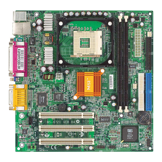
ATX1 JCASE1 Top : Game port BIOS Winbond Bottom: W83697HF Line-Out Line-In JCD1 Codec JAUD 1 650GLMS (MS-6721) v1.X Micro ATX Mainboard 650GL PCI Slot 1 PCI Slot 2 PCI Slot 3 JFP2 JUSB1 SYSFAN1 CPUFAN1 BATT JBAT1 962L JSMI1... -
Page 12: Msi Special Features
MSI Special Features PC Alert™ 4 The PC Alert 4 is a utility you can find in the CD-ROM disk. The utility is just like your PC doctor that can detect the following PC hardware status during real time operation: monitor CPU &... - Page 13 650GLMS Micro ATX Mainboard To better protect the CPU from overheating, a new feature, COOLER XP, has been added to decrease the temperature of AMD Athlon XP CPU. To do so, simply click COOLER XP and the screen will show the Cute skin (as shown below) with information about the CPU and chipset.
-
Page 14: Live Bios™/Live Driver
BIOS/drivers online so that you don’t need to search for the correct BIOS/driver version throughout the Web site. To use the function, you need to install the “MSI Live Update 2” application. After the installation, the “MSI Live Update 2”... -
Page 15: Live Monitor
Live Monitor™ The Live Monitor™ is a tool used to schedule the search for the latest BIOS/drivers version on the MSI Web site. To use the function, you need to install the “MSI Live Update Series 2” application. After the installation, the “MSI Live Monitor” icon (as shown on the right) will appear on the screen. -
Page 16: Chapter 2. Hardware Setup
Chapter 2. Hardware Setup Hardware Setup This chapter tells you how to install the CPU, memory modules, and expansion cards, as well as how to setup the jump- ers on the mainboard. Also, it provides the instructions on con- necting the peripheral devices, such as the mouse, keyboard, etc. -
Page 17: Quick Components Guide
650GLMS Micro ATX Mainboard Quick Components Guide ATX1, p.2-9 Back Panel I/O, p.2-11 JCASE1, p.2-18 JCD1, p.2-18 PCI Slots, p.2-23 JAUD1, p.2-20 CPU, p.2-3 JUSB1, p.2-21 JFP2, p.2-19 DDR DIMMs, p.2-7 CONN1, p.2-9 SYSFAN1, p.2-15 FDD1, p.2-15 CPUFAN1, p.2-17 IDE1, IDE2, p.2-16... -
Page 18: Central Processing Unit: Cpu
CPU Core Speed Derivation Procedure CPU Clock Core/Bus ratio then CPU core speed MSI Reminds You... Overheating Overheating will seriously damage the CPU and system, al- ways make sure the cooling fan can work properly to protect the CPU from overheating. -
Page 19: Cpu Installation Procedures For Socket 478
650GLMS Micro ATX Mainboard CPU Installation Procedures for Socket 478 Please turn off the power and unplug the power cord before installing the CPU. Pull the lever sideways away from the socket. Make sure to raise the lever up to a 90- degree angle. -
Page 20: Installing The Cpu Fan
CPU cooling fan and heatsink on top of the CPU. Follow the instructions below to install the Heatsink/Fan: Locate the CPU and its retention mechanism on the motherboard. retention mechanism Mount the fan on top of the heatsink. - Page 21 650GLMS Micro ATX Mainboard Connect the fan power cable from the mounted fan to the 3-pin fan power connector on the board. fan power cable NOTES...
-
Page 22: Memory
The mainboard provides 2 sockets for 168-pin unbuffered SDRAM DIMM (Double In-Line Memory Module) modules and supports a maximum memory size of 2GB. Introduction to SDRAM Synchronous DRAM (SDRAM) is a type of dynamic RAM memory chip that has been widely used starting in the latter part of the 1990s. SDRAMs are based on standard dynamic RAM chips, but have sophisticated features that make them considerably faster. -
Page 23: Installing Dimm Modules
650GLMS Micro ATX Mainboard DIMM Module Combination At least one DIMM module should be installed on the motherboard. Memory modules can be installed on the slots in any order. The single-/ double-sided memory modules that each DIMM slot supports are listed as... -
Page 24: Power Supply
The mainboard supports ATX power supply for the power system. Be- fore inserting the power supply connector, always make sure that all compo- nents are installed properly to ensure that no damage will be caused. ATX 20-Pin Power Connector: CONN1 This connector allows you to connect to an ATX power supply. -
Page 25: Back Panel
650GLMS Micro ATX Mainboard The back panel provides the following connectors: Mouse (Optional) Keyboard USB Ports COMA Mouse Connector The mainboard provides a standard PS/2 ® for attaching a PS/2 mouse. You can plug a PS/2 connector. The connector location and pin assignments are as follows:... -
Page 26: Keyboard Connector
Keyboard Connector The mainboard provides a standard PS/2 ® tor for attaching a PS/2 keyboard. You can plug a PS/2 into this connector. PS/2 Keyboard (6-pin Female) USB Connectors The mainboard provides a UHCI (Universal Host Controller Interface) Universal Serial Bus root for attaching USB devices such as keyboard, mouse or other USB-compatible devices. -
Page 27: Serial Port Connectors: Coma
650GLMS Micro ATX Mainboard Serial Port Connectors: COMA The mainboard offers one 9-pin male DIN connector as serial port COM A. This port is 16550A high speed communication ports that send/receive 16 bytes FIFOs. You can attach a serial mouse or other serial device directly to it. -
Page 28: Lan Jack (Optional)
RJ-45 LAN Jack (Optional) The mainboard provides one standard RJ-45 jack for connection to Lo- cal Area Network (LAN). You can connect a network cable to the LAN jack. RJ-45 LAN Jack Midi/Joystick Connector You can connect a joystick or game pad to this connector. Audio Port Connectors Line Out is a connector for Speakers or Headphones. -
Page 29: Parallel Port Connector: Lpt1
650GLMS Micro ATX Mainboard Parallel Port Connector: LPT1 The mainboard provides a 25-pin female centronic connector as LPT. A parallel port is a standard printer port that supports Enhanced Parallel Port (EPP) and Extended Capabilities Parallel Port (ECP) mode. SIGNAL... -
Page 30: Internal Connectors
The mainboard provides connectors to connect to FDD, IDE HDD, case, modem, LAN, USB Ports, IR module and CPU/System/Power Supply FAN. Floppy Disk Drive Connector: FDD1 The mainboard provides a standard floppy disk drive connector that supports 360K, 720K, 1.2M, 1.44M and 2.88M floppy disk types. Power Saving Switch Connector Connector: JSMI1 Attach a power saving switch to this connector. -
Page 31: Hard Disk Connectors: Ide1 & Ide2
650GLMS Micro ATX Mainboard Hard Disk Connectors: IDE1 & IDE2 The mainboard has a 32-bit Enhanced PCI IDE and Ultra DMA 66/100/ 133 controller that provides PIO mode 0~4, Bus Master, and Ultra DMA 66/ 100/133 function. You can connect up to four hard disk drives, CD-ROM, 120MB Floppy (reserved for future BIOS) and other devices. -
Page 32: Fan Power Connectors: Cpufan1/Sysfan1
CPU fan control. MSI Reminds You... 1. Always consult the vendors for proper CPU cooling fan. 2. CPUFAN1 supports the fan control. You can install the PC Alert utility that will automatically control the CPU fan speed according to the actual CPU temperature. -
Page 33: Cd-In Connector: Jcd1
650GLMS Micro ATX Mainboard CD-In Connector: JCD1 The connector is for CD-ROM audio connector. JCD1 Chassis Intrusion Switch Connector: JCASE1 This connector is connected to a 2-pin chassis switch. If the chassis is opened, the switch will be short. The system will record this status and show a warning message on the screen. -
Page 34: Front Panel Connectors: Jfp1 & Jfp2
Front Panel Connectors: JFP1 & JFP2 The mainboard provides two front panel connectors for electrical con- nection to the front panel switches and LEDs. JFP1 is compliant with Intel Front Panel I/O Connectivity Design Guide. SIGNAL HD_LED_P FP PWR/SLP HD_LED_N FP PWR/SLP RST_SW_N PWR_SW_P... -
Page 35: Front Panel Audio Connector: Jaud1
650GLMS Micro ATX Mainboard Front Panel Audio Connector: JAUD1 The JAUD1 front panel audio connector allows you to connect to the front panel audio and is compliant with Intel Design Guide. JAUD1 SIGNAL AUD_MIC AUD_GND AUD_MIC_BIAS AUD_VCC AUD_FPOUT_R AUD_RET_R HP_ON... -
Page 36: Front Usb Connectors: Jusb1
Front USB Connectors: JUSB1 The mainboard provides one USB 2.0 pin header JUSB1 that is compliant ® with Intel I/O Connectivity Design Guide. USB 2.0 technology increases data transfer rate up to a maximum throughput of 480Mbps, which is 40 times faster than USB 1.1, and is ideal for connecting high-speed USB inter- face peripherals such as USB HDD, digital cameras, MP3 players, printers, modems and the like. -
Page 37: Jumpers
650GLMS Micro ATX Mainboard The motherboard provides the following jumpers for you to set the computer’s function. This section will explain how to change your motherboard’s function through the use of jumpers. Clear CMOS Jumper: JBAT1 There is a CMOS RAM on board that has a power supply from external battery to keep the data of system configuration. -
Page 38: Slots
The motherboard provides three 32-bit PCI bus slots. PCI Slots PCI (Peripheral Component Interconnect) Slots The PCI slots allow you to insert the expansion cards to meet your needs. When adding or removing expansion cards, make sure that you unplug the power supply first. -
Page 39: Chapter 3. Bios Setup
Chapter 3. BIOS Setup BIOS Setup This chapter provides information on the BIOS Setup program and allows you to configure the system for optimum use. You may need to run the Setup program when: An error message appears on the screen during the system booting up, and requests you to run SETUP. -
Page 40: Entering Setup
650GLMS Micro ATX Mainboard KT3 Ultra2-C ATX Mainboard Power on the computer and the system will start POST (Power On Self Test) process. When the message below appears on the screen, press <DEL> key to enter Setup. Press DEL to enter SETUP If the message disappears before you respond and you still wish to enter Setup, restart the system by turning it OFF and On or pressing the RESET button. -
Page 41: Getting Help
Press <Esc> to exit the Help screen. MSI Reminds You... The items under each BIOS category described in this chapter are under continuous update for better system performance. -
Page 42: The Main Menu
650GLMS Micro ATX Mainboard KT3 Ultra2-C ATX Mainboard The Main Menu ® Once you enter Award BIOS CMOS Setup Utility, the Main Menu (Figure 1) will appear on the screen. The Main Menu allows you to select from twelve setup functions and two exit choices. Use arrow keys to select among the items and press <Enter>... - Page 43 BIOS Setup Frequency/Voltage Control Use this menu to specify your settings for frequency/voltage control. Load Fail-Safe Defaults Use this menu to load the BIOS values for the best system performance, but the system stability may be affected. Load Optimized Defaults Use this menu to load factory default settings into the BIOS for stable system performance operations.
-
Page 44: Standard Cmos Features
650GLMS Micro ATX Mainboard KT3 Ultra2-C ATX Mainboard Standard CMOS Features The items in Standard CMOS Features Menu are divided into 11 categories. Each category includes no, one or more than one setup items. Use the arrow keys to highlight the item and then use the <PgUp> or <PgDn> keys to select the value you want in each item. - Page 45 ing items. Enter the information directly from the keyboard. This informa- tion should be provided in the documentation from your hard disk vendor or the system manufacturer. Access Mode Capacity Cylinder Head Precomp Landing Zone Sector Drive A/B This item allows you to set the type of floppy drives installed. Available options: None, 360K, 5.25 in., 1.2M, 5.25 in., 720K, 3.5 in., 1.44M, 3.5 in., 2.
-
Page 46: Advanced Bios Features
650GLMS Micro ATX Mainboard KT3 Ultra2-C ATX Mainboard Advanced BIOS Features Quick Boot Setting the item to Enabled allows the system to boot within 5 seconds since it will skip some check items Settings: Disabled, Enabled. Anti-Virus Protection The item is to set the Virus Warning feature for IDE Hard Disk boot sector protection. - Page 47 USB-ZIP USB-CDROM USB-HDD Disabled MSI Reminds You... Available settings for “1st/2nd/3rd Boot Device” vary depend- ing on the bootable devices you have installed. For example, if you did not install a floppy drive, the setting “Floppy” does not show up.
- Page 48 650GLMS Micro ATX Mainboard KT3 Ultra2-C ATX Mainboard Gate A20 Option This item is to set the Gate A20 status. A20 refers to the first 64KB of extended memory. When the default value Fast is selected, the Gate A20 is controlled by Port92 or chipset specific method resulting in faster system performance.
- Page 49 BIOS Setup MPS Table Version This field allows you to select which MPS (Multi-Processor Specification) version to be used for the operating system. You need to select the MPS version supported by your operating system. To find out which version to use, consult the vendor of your operating system.
-
Page 50: Advanced Chipset Features
650GLMS Micro ATX Mainboard KT3 Ultra2-C ATX Mainboard Advanced Chipset Features MSI Reminds You... Change these settings only if you are familiar with the chipset. Advanced DRAM Control 1 Press <Enter> and the following sub-menu appears: System Performance The field specifies the System Performance Mode. Settings: Safe Mode, Normal Mode, Fast Mode, Turbo Mode, and Ultra Mode. - Page 51 CAS Latency Setting The field controls the CAS latency, which determines the timing delay before SDRAM starts a read command after receiving it. Setting options: By SPD, 3T, 2.5T, 2T. 2T increases system performance while 2.5T provides more stable system performance. Setting to By SPD enables DRAM CAS# Latency automatically to be determined by BIOS based on the configurations on the SPD (Serial Presence Detect) EEPROM on the DRAM module.
-
Page 52: Integrated Peripherals
650GLMS Micro ATX Mainboard KT3 Ultra2-C ATX Mainboard Integrated Peripherals SiS On-Chip IDE Device Press <Enter> and the following sub-menu appears: Internal PCI/IDE The field specifies the internal primary and secondary PCI/IDE controllers. Settings: Disabled, Primary, Secondary, Both. IDE Primary/Secondary Master/Slave PIO... - Page 53 Primary/Secondary Master/Slave UltraDMA Ultra DMA 33/66/100/133 implementation is possible only if your IDE hard drive supports it and the operating environment includes a DMA driver (Windows ME, XP or a third-party IDE bus master driver). If your hard drive and your system software both support Ultra DMA/33, Ultra DMA/66, Ultra DMA/100 and Ultra DMA/133, select Auto to enable BIOS support.
- Page 54 650GLMS Micro ATX Mainboard KT3 Ultra2-C ATX Mainboard SiS AC’97 Audio Auto allows the mainboard to detect whether an audio device is used. If an audio device is detected, the onboard AC’97 (Audio Codec’97) controller will be enabled; if not, it is disabled. Disable the controller if you want to use other controller cards to connect an audio device.
- Page 55 BIOS to automatically determine the correct base I/O port address. Settings: Disabled, 3F8/IRQ4, 2F8/IRQ3, 3E8/IRQ4, 2E8/IRQ3, Auto. Onboard Parallel Port This specifies the I/O port address and IRQ of the onboard parallel port. Settings: 378/IRQ7, 278/IRQ5, 3BC/IRQ7, Disabled. Parallel Port Mode This item selects the operating mode for the parallel port: Normal, SPP, EPP, ECP, or ECP+EPP.
-
Page 56: Power Management Setup
650GLMS Micro ATX Mainboard KT3 Ultra2-C ATX Mainboard Power Management Setup IPCA Function This item is to activate the ACPI (Advanced Configuration and Power Management Interface) Function. If your operating system is ACPI-aware, ® such as Windows 98SE/2000/ME/XP, select Enabled. Settings: Enabled, Disabled. - Page 57 Suspend Mode When you choose User Define in the Power Management item, this item is selectable. This setting allows you to select the type of Suspend mode. Setting options: Disabled (default setting), 1 min to 1 hour. MODEM Use IRQ This setting names the interrupt request (IRQ) line assigned to the modem (if any) on your system.
- Page 58 650GLMS Micro ATX Mainboard KT3 Ultra2-C ATX Mainboard Last State Restores the system to the status before power failure or interrupt occurred. PM Wake Up Events Press <Enter> and the following sub-menu appears: MSI Reminds You... S3-related functions described in this section are available only when your BIOS supports S3 sleep mode.
- Page 59 saving modes when activity or input signal of the specified hardware peripheral or component is detected. Settings: Enabled, Disabled. PS2KB/PS2MS Wake Up From S3 These fields controls how the PS2 keyboard/mouse can power on the system. Settings: Disabled, Enabled. Resume By Alarm The field is used to enable or disable the function of Resume By Alarm.
-
Page 60: Pnp/Pci Configurations
650GLMS Micro ATX Mainboard KT3 Ultra2-C ATX Mainboard PNP/PCI Configurations This section describes configuring the PCI bus system and PnP (Plug & Play) feature. PCI, or Peripheral Component Interconnect, is a system which allows I/O devices to operate at speeds nearing the speed the CPU itself uses when communicating with its special components. - Page 61 IRQ/DMA Resources The items are adjustable only when Resources Controlled By is set to Manual. Press <Enter> and you will enter the sub-menu screen. IRQ Resources list IRQ-3/4/5/7/9/10/11/12/14/15 and DMA Resources list DMA-0/1/3/5/6/7 for users to set each IRQ/DMA a type depending on the type of device using the IRQ/DMA.
-
Page 62: Pc Health Status
650GLMS Micro ATX Mainboard KT3 Ultra2-C ATX Mainboard PC Health Status This section shows the status of your CPU, fan, overall system status, etc. Monitor function is available only if there is hardware monitoring mechanism onboard. Case Open Warning The field enables or disables the feature of recording the chassis intrusion status and issuing a warning message if the chassis is once opened. -
Page 63: Frequency/Voltage Control
Set CPU Ratio This setting controls the multiplier that is used to determine the internal clock speed of the processor relative to the external or motherboard clock speed. Auto Detect DIMM/PCI Clk This item is used to auto detect the DIMM/PCI slots. When set to Enabled, the system will remove (turn off) clocks from empty DIMM/PCI slots to minimize the electromagnetic interference (EMI). -
Page 64: Load Fail-Safe/Optimized Defaults
650GLMS Micro ATX Mainboard KT3 Ultra2-C ATX Mainboard Load Fail-Safe/Optimized Defaults The two options on the main menu allow users to restore all of the BIOS settings to the default Fail-Safe or Optimized values. The Optimized Defaults are the default values set by the mainboard manufacturer specifically for optimal performance of the mainboard. -
Page 65: Set Supervisor/User Password
Security Option is set to System, the password is required both at boot and at entry to Setup. If set to Setup, password prompt only occurs when you try to enter Setup. MSI Reminds You... About Supervisor Password & User Password: Supervisor password:... -
Page 66: Troubleshooting
Q: How do I know what MSI D-LED or D-bracket light mean? A: Please follow the special tech issue, http://www.msi.com.tw/support/ techexpress/special_tech/smartled.htm Q: I have got MSI Motherboard and when it says detecting drives, it detects them but says an error saying "Primary IDE Channel no 80 Conductor Cable Installed"... - Page 67 2. Try to clear the CMOS If problem still persists, ask your reseller for new BIOS chip or contact one of MSI office near your place for new BIOS chip http:// www.msi.com.tw/contact/main.htm Q: Should I update my BIOS, once a new BIOS is released? A: A new BIOS is usually released due to the following reasons: 1.
- Page 68 BIOS, unless you really have to. Q: How do I update the BIOS? A: Please refer to http://www.msi.com.tw/support/bios/note.htm for details. Q: How do I identify the BIOS version? A: Upon boot-up, the 1st line appearing after the memory count is the BIOS version.
- Page 69 650GLMS Micro ATX Mainboard Q: After flashing the bios and rebooting the system, the screen went blank. A: For AMI BIOS Rename the desired AMI BIOS file to AMIBOOT.ROM and save it on a floppy disk. e.g. Rename A569MS23.ROM to AMIBOOT.ROM Insert this floppy disk in the floppy drive.
-
Page 70: Glossary
Glossary Glossary Glossary ACPI (Advanced Configuration & Power Interface) This power management specification enables the OS (operating system) to control the amount of power given to each device attached to the computer. Windows 98/98SE, Windows 2000 and Windows ME can fully support ACPI to allow users managing the system power flexibly. - Page 71 650GLMS Micro ATX Mainboard contents of frequently accessed RAM locations and the addresses where these data items are stored. Chipset A collection of integrated chips designed to perform one or more related functions. For example, a modem chipset contains all the primary circuits for transmitting and receiv- ing data;...
- Page 72 Glossary ECC Memory (Error Correcting Code Memory) A type of memory that contains special circuitry for testing the accuracy of data and correcting the errors on the fly. EEPROM Acronym for Electrically Erasable Programmable Read-Only Memory. An EEPROM is a special type of PROM that can be erased by exposing it to an electrical charge. Like other types of PROM, EEPROM retains its contents even when the power is turned off.
- Page 73 ISA is a standard bus (computer interconnection) architecture that is associated with the IBM AT motherboard. It allows 16 bits at a time to flow between the motherboard circuitry and an expansion slot card and its associated device(s). Also see EISA and MCA.
- Page 74 Glossary LBA (Logical Block Addressing) Logical block addressing is a technique that allows a computer to address a hard disk larger than 528 megabytes. A logical block address is a 28-bit value that maps to a specific cylinder-head-sector address on the disk. 28 bits allows sufficient variation to specify addresses on a hard disk up to 8.4 gigabytes in data storage capacity.
- Page 75 650GLMS Micro ATX Mainboard PS/2 Port A type of port developed by IBM for connecting a mouse or keyboard to a PC. The PS/2 port supports a mini DIN plug containing just 6 pins. Most modern PCs equipped with PS/2 ports so that the special port can be used by another device, such as a modem.
Need help?
Do you have a question about the 650GLMS and is the answer not in the manual?
Questions and answers