Soyal AR-721U User Manual
Hide thumbs
Also See for AR-721U:
- Manual (4 pages) ,
- Hardware operation manual (7 pages) ,
- Manual (4 pages)
Table of Contents
Advertisement
Quick Links
Advertisement
Table of Contents

Related Manuals for Soyal AR-721U


Summary of Contents for Soyal AR-721U
- Page 1 AR-721U/721K/661U User’s Guide Feb. 6, 2004...
-
Page 2: Table Of Contents
2.4 PCB board ----------------------------------8 2.4.1 No waterproof --------------------------------- 8 2.4.2 Waterproof --------------------------------- 8 2.5 Installation diagram ----------------------------------9 2.5.1 AR-721U & AR-721H ------------------- 9 2.5.2 AR-721U & AR-727H ------------------- 10 2.5.3 AR-721U & AR-821EF ------------------- 11 2.5.4 AR-721U & AR-829E ------------------- 12... - Page 3 AR-661U Installation -------------------------------- 21 4.1 Installation Notice -------------------------------- 21 4.2 Wiring -------------------------------- 22 4.3 Installation diagram -------------------------------- 23 4.3.1 AR-661U & AR-721H ------------------- 23 4.3.2 AR-661U & AR-727H ------------------- 24 4.3.3 AR-661U & AR-821EF ------------------- 25 4.3.4 AR-661U & AR-829E ------------------- 26 4.4 The standalone controller do anti-pass-back with 2 pcs of AR-661U...
-
Page 4: Main Feature
1. Main Features Easily integrated with soyal or other access control systems. Programmable various outputs formats Wiegand, magstripe or serial. Built-in watchdog to prevent the system from halting A bi-color LED indicator and a beep sound. Item AR-721U AR-721K AR-661U... -
Page 5: Ar-721U Installation
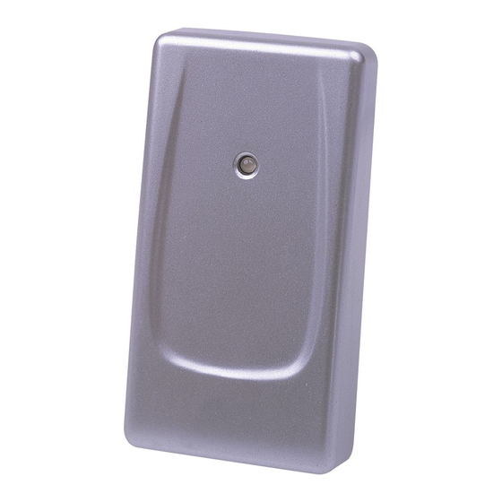
1. Use the screwdriver to screw the mounting plate on the wall. 2. Pull cable ends through the access hole in the mounting plate. AR-721U must be connected before power is applied to the single door controller. 3. Attach the AR-721U to the mounting plate. -
Page 6: Installation Notice
50 cm above and 12 m below (suggestion value). 3. Normally, AR-721U will read a Card / Key Tag at up to 8 cm. However, when AR-721U reader is mounted directly on a metal surface, the reading distance decreases slightly. To reduce this effect, install wood or plastic between the mounting surface and mounting plate, this will restore most of the reading distance. -
Page 7: Wiring
2.3 Wiring Table 1 - Color Coding Wire Application Wire Color Description DC Power 12V Power Black DC Power 0V Yellow LED Red Input ( Low Bright) Brown LED Green Input ( Low Bright) Blue Wiegand DAT:1 Wiegand Green Wiegand DAT:0 Purple Beeper Input ( Low Sound ) Beeper White Card Present... - Page 8 AR-721U RS-232 Format: ( 9600,N, 8, 1 SOYAL Format ) DAT:0: TTL Inverted Serial Output. ( Can connect to PC comm port ) DAT:1: TTL Serial Output. ( connect to PC comm. port through RS-232 invert driver )
-
Page 9: Pcb Board
2.4 PCB board 2.4.1 No waterproof Output Format 34126 34126 (Default) WG 26 34126 WG 34 721U PCB 34126 RS-232 34126 Buzzer 2.4.2 Waterproof Output Format Connect for WG34 bit (Default) Cut for WG26 bit Buzzer AR-721U... -
Page 10: Installation Diagram
2.5 Installation diagram 2.5.1 AR-721U & AR-721H... -
Page 11: Ar-721U & Ar-727H
2.5.2 AR-721U & AR-727H 727H Black... -
Page 12: Ar-721U & Ar-821Ef
2.5.3 AR-721U & AR-821EF... -
Page 13: Ar-721U & Ar-829E
2.5.4 AR-721U & AR-829E 829E Black... -
Page 14: Ar-721K Installation
3 . AR-721K Installation 3.1 Steps 1. Use the screwdriver to screw the mounting plate on the wall. 2. Pull cable ends through the access hole in the mounting plate. AR-721K must be connected before power is applied to the single door controller. -
Page 15: Installation Notice
3.2 Installation Notice 1. Single door controller locate inside the secure area for use as an exit controller, the auxiliary reader locate exterior wall for use as an entrance reader, but not directly behind single door controller. For best reading distance, offset the single door controller and auxiliary reader by about 50 cm above and 12 m below (suggestion value). -
Page 16: Wiring
3.3 Wiring Table 1 - Connector P1 Color Coding Wire Application Wire Color Description Thick Red DC Power 12V Power Thick Black DC Power 0V Table 2 - Connector P2 Color Coding (Wiegand Read Head ) Wire Application Wire Color Description Thin Blue Wiegand DAT:1 Input... -
Page 17: Pcb Board
Table 3 - Connector P3 Color Coding (Tamper Switch ) Wire Application Wire Color Description Tamper Switch N.C. Orange Yellow N.O. 3.4 PCB board Output Format BIT(26/34) WG 26 (Default) Buzzer BIT(26/34) WG 34 721K 1FF9 WG J1 BIT(26/34) WG 34 BIT(26/34) ABA 10 SOYAL Format (Default) EM Format... -
Page 18: Installation Diagram
3.5 Installation diagram 3.5.1 AR-721K & AR-721H... -
Page 19: Ar-721K & Ar-727H
3.5.2 AR-721K & AR-727H 727H Black... -
Page 20: Ar-721K & Ar-821Ef
3.5.3 AR-721K & AR-821EF...
Need help?
Do you have a question about the AR-721U and is the answer not in the manual?
Questions and answers