Table of Contents
Advertisement
Quick Links
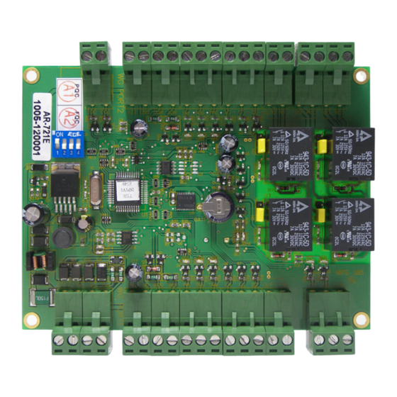
SOYAL
ACCESS CONTROL SYSTEM
Contents
1
Product
Specifi cation
CPU
8 bit CPU
RAM
512 k Bits
Power Supply
10 ~ 24
Power Consumption
< 3W
Interface
RS-485
Baud Rate
9600 bps,N,8,1
External WG Readers
2 WG
(Controller power supply)
Connector Table
P6
P5
2 1
12 11 10 9 8 7 6 5 4 3 2 1
ON
1
2
3
4
N.O.
Dip-switch
N.O.
4 3 2 1
12 11 10 9 8 7 6 5 4 3 2 1
P1
P2
Node ID is setting by DIP_Switch
ON
Node ID: 01~16
1
2
3
4
DIP SW
1
2
Node ID 01
ON
off
Node ID 02
off
ON
Node ID 03
ON
ON
Node ID 15
ON
ON
Node ID 16
off
off
Wiring Diagram
P1
AR-321H
Connect to PC
Converter
B-
A+
®
2
User Guide
3
Specifi cation
Separate controller connected to 2 WG readers, can enhance the security of the system.
Can connect to Door Open Button, Door Sensor, and Tamper Switch.
When Door open to Long or Force open, it's can be detected.
4 Control Mode, allowing users the fl exibility of use with.
Can automatically determine to use stand-alone or networking.
Temperature
Digital Input
Relpy Output
Transistor Output
Door Relay Time
Alarm Relay Time
User Capacity
P4
Connector:
4 3 2 1
Code
LA+
LB-
OUT 2
DO 1
GND
DC 12V
N.O.
OUT 1
ALM
Connector:
Code
N.O.
COM
3 2 1
OUT1
P3
BZ
LG
LR
TAM
SEN
PB
WD1
WD0
3
4
GND
off
off
12V
off
off
Connector:
off
off
Code
COM
ON
ON
DI2
off
off
DI1
12V
GND
AR-721E
P1
12V
B-
A+
4 3 2 1
AR-721E
-20℃ ~ +60℃
2 Door Open Button/ 2 Door Sensor/ 2 Housing open detection/ Prepared for 2 DI
2 Door Relay/ 1 Alarm Relay/ Prepared for 1 Relay output
Prepared for 2 DO
Toggle, 0.1~600Ses
Toggle, 0.1~600Ses
3,000
P1
Pin
Description
1
RS-485(A+)
2
RS-485(B-)
3
DC Power 0V
4
DC Power 12V
P2
Pin
Description
1
COM
2
N.C./N.O.
3
Beeper Output
4
LED Green Output
5
LED Red Output
6
Tamper Switch Input
7
Door Sensor Input
8
Exit Switch Input
9
Wiegand DAT:1 Input
10
Wiegand DAT:0 Input
11
DC Power 0V Output
12
DC Power 12V Output
P3
Pin
Description
1
COM
2
DI 2
3
Fire-alarm Input
P4
Connect to Alarm or Other Equipment
POWER
Equipment
12VDC
Alarm
Event log
1456
Aux. WG Port
WG 26 / WG 34
YES
Lift Control
NO
Time Zone
63
Real Time Clock
YES
DIP_SW
4
(Node ID: 1~16)
Connector:
P4
Code
Pin
Description
COM
1
COM
DO1
2
N.C./N.O.
COM
3
COM
ALM
4
N.C./N.O.
Connector:
P5
Code
Pin
Description
COM
1
COM
OUT2
2
N.C./N.O.
BZ
3
Beeper Output
LG
4
LED Green Output
LR
5
LED Red Output
TAM
6
N.C.
SEN
7
N.C.
PB
8
N.O.
WD1
9
Wiegand DAT:1 Input
WD0
10
Wiegand DAT:0 Input
GND
11
DC Power 0V Output
12V
12
DC Power 12V Output
Connector:
P6
Code
Pin
Description
DO3
1
DO 3
DO2
2
DO 2
12V
POWER
GND
12VDC
4 3 2 1
AR-721E
P4
V100630
(stand-alone /networking)
Advertisement
Table of Contents

Subscribe to Our Youtube Channel
Related Manuals for Soyal AR-721E


Summary of Contents for Soyal AR-721E
- Page 1 SOYAL ® AR-721E V100630 ACCESS CONTROL SYSTEM Contents Product User Guide Specifi cation Separate controller connected to 2 WG readers, can enhance the security of the system. Can connect to Door Open Button, Door Sensor, and Tamper Switch. When Door open to Long or Force open, it's can be detected.
- Page 2 12 11 10 9 8 7 6 5 4 3 2 1 Push Button Push Button AR-721E AR-721E Reader ※ Notice If the Power line more than 100 m between the Controller and Reader, it is recommended NOT to use the "Wiegand Power".
- Page 3 SOYAL ® AR-721E V100630 ACCESS CONTROL SYSTEM B. Chang the Node ID of Reader Access programming mode → 00 [Node ID: 001~255] C.Set up M4/M8 Access programming mode → 04 [N=4/8] D. Set up the password Card or PIN: Access programming mode → 12...
- Page 4 2 Door WG Controller V100630 ※Default Value Function Selection Value Application Can be password-free in the Card or PIN mode ※0: Disable 1: Enable Networking/Stand-Alone Reset the Anti-pass-back by the software ※0: Disable 1: Enable Networking/Stand-Alone Arming for force open ※0: Disable 1: Enable Networking/Stand-Alone...
Need help?
Do you have a question about the AR-721E and is the answer not in the manual?
Questions and answers