Advertisement
Available languages
Available languages
Quick Links
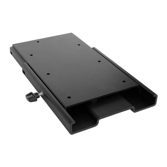
For use with all Minn Kota® PowerDrive™, Pontoon PowerDrive™, Ulterra™ and Terrova® freshwater trolling motors, the PowerDrive™ Pontoon
Hand Control Bracket and the DeckHand 40.
Item /
Part #
Description
Assembly
A
Includes
2990114
QCK REL PLATE/THUMB SCREW ASM
2-10
✖
2
PLATE-MNT,TOP PD QUICK RELEASE
✖
4
PLATE-MNT,BTM PD/AP QK/RL
6
2373421
SCREW-5/16-18 X 3/8 SHCS S/S
8
9951778
LOCKWASHER-1/4" ZINC
10
2011385
SCREW-TENSION/NEW KNOB
p
2374914
INSTR SHEET-PD/AP QK RL BRK
B
Includes
2994932
BAG ASM, ELEC. STEER QRB
12-18
12
2371728
WASHER-FENDER 1/4 X 1 1/4 ZP
14
2373413
SCREW-1/4-20 X 7/8 HHCS ZP
16
2263104
NUT-1/4-20 NYLOCK ZP
18
2373516
BOLT-1/4-20 X 2" HHC ZP
p
Not shown on Parts Diagram.
✖ This part is included in an assembly and cannot be ordered individually.
TOOLS AND RESOURCES REQUIRED
• #3 Phillips Screwdriver
• Drill
MOUNTING CONSIDERATIONS
It is recommended that the motor be mounted as close to the
centerline or keel of the boat as possible. The motor must not
encounter any obstructions as it is lowered into the water or raised
into the boat when stowed and deployed. Make sure the motor rest
is positioned far enough beyond the edge of the boat. Make sure
the area under the mounting location is flat, clear to drill holes and
install nuts and washers. Recruit a second person to help with the
installation, as an unsecured motor will tip when deployed and
when left unattended.
The mounting surface for the Bottom Plate must
NOTICE:
be completely flat. Rubber Washers can be used to shim
the Bottom Plate flat before hardware is tightened.
In order for the MKA-16-03 bracket to be engaged
NOTICE:
and disengaged, the motor must be in the stowed position.
1 | minnkotamotors.com
Qty.
1
1
1
1
1
1
1
1
4
4
8
4
• 9/32" Drill Bit
• Awl or similar marking tool
MKA-16-03 ELECTRIC-STEER
QUICK RELEASE BRACKET
B B
18
18
14
14
12
12
16
16
A A
6 6
• 7/16" Box End or
Open End Wrench
Complete Typical Installation
Images are a graphical representation and may
NOTICE:
vary slightly from your motor.
1854035
2 2
4 4
10
10
• A second person to help
with the installation
©2022 Johnson Outdoors Marine Electronics, Inc.
8 8
Advertisement

Related Manuals for MINN KOTA MKA-16-03


Summary of Contents for MINN KOTA MKA-16-03
- Page 1 MKA-16-03 ELECTRIC-STEER QUICK RELEASE BRACKET 1854035 For use with all Minn Kota® PowerDrive™, Pontoon PowerDrive™, Ulterra™ and Terrova® freshwater trolling motors, the PowerDrive™ Pontoon Hand Control Bracket and the DeckHand 40. Item / Part # Description Qty. Assembly Includes 2990114...
- Page 2 The MKA-16-03 Electric Steer Quick Release Bracket is designed to work on a number of Minn Kota trolling motors. The base extrusion or mounting bracket of the trolling motors may vary. Please note the appearance of the applicable trolling motors and mounting brackets.
-
Page 3: Installation
Slide the Plates completely apart and set the Bottom Plate aside. The Top Plate will be installed first. CAUTION Watch for pinch points when sliding the Top and Bottom Plates of the MKA-16-03. On the Top Plate, take note of the Padlock Slot on Top Plate Top Plate... - Page 4 Stowed Deployed Deployed Sideplate Screw Sideplate Screw A motor may weigh up to 65lbs. Minn Kota NOTICE: recommends having a second person help with the installation. Remove the Right Sideplate. Swing the Left Sideplate out and away from the Base Extrusion.
- Page 5 ITEM(S) NEEDED #2 x 1 #14 x 4 #16 x 4 Place the flat side of the Top Plate (Item #2) against Base Base Nylock Nuts Nylock Nuts Outboard Outboard the bottom of the Base Extrusion. The Padlock Slot Extrusion Extrusion on the Top Plate should face inboard.
- Page 6 Installing the Top Plate to a DeckHand 40 ITEM(S) NEEDED #2 x 1 #14 x 4 #16 x 4 For more detailed instructions on installing a Outboard Outboard NOTICE: Davit Davit Base Base DeckHand 40, refer to the DeckHand 40 owner's manual online at minnkotamotors.com.
- Page 7 The motor should be in the stowed position. Stowed Stowed Deployed Deployed A motor may weigh up to 65lbs. Minn Kota NOTICE: recommends having a second person help with the installation. This installation requires the use of hardware NOTICE: WARNING that was included with the Ulterra motor.
- Page 8 Under the Left Sideplate, the Extension Damper obstructs access to the front-left Mounting Hole. Using a small Screwdriver, remove the two 5/16" E-clips holding the Extension Damper in place. Once the E-clips are removed, slide the Extension Damper off the Damper Pins to expose the blocked Mounting E-clip E-clip Hole.
- Page 9 Slide the Base Extrusion into place on the Screws that were just installed. The Base Extrusion should slide between the Top Plate and the Clipped Washers. Hold the Clipped Washers up on the Screws so that the Clipped Washers will sit on top of the Base Extrusion.
- Page 10 Deck of boat, boat deck, and which base extrusion or bracket the Boat Boat MKA-16-03 is being mounted to. The Ulterra motor cannot be deployed before mounting and connecting a power source. 10 | minnkotamotors.com ©2022 Johnson Outdoors Marine Electronics, Inc.
- Page 11 With a mounting location determined and all Outboard Outboard Outboard Outboard clearances confirmed, use an Awl or similar tool to Bow of Bow of Bottom Bottom mark the side and rear edges of the Bottom Plate on Boat Boat Plate Plate the bow of the boat.
-
Page 12: Completing The Installation
Tension Tension Screw Knob Screw Knob For warranty information, please visit minnkotamotors.com. Minn Kota Consumer & Technical Service 121 Power Drive Johnson Outdoors Marine Electronics, Inc. Mankato, MN 56001 PO Box 8129 Phone (800) 227-6433 ©2022 Johnson Outdoors Marine Electronics, Inc. - Page 13 SUPPORT À DÉGAGEMENT RAPIDE À COMMANDE ÉLECTRIQUE MKA-16-03 1854035 À utiliser avec tous les moteurs de pêche à la traîne pour eau douce Minn Kota® Powerdrive™, Pontoon PowerDrive™, Ulterra™ et Terrova®, le support à commande manuelle de PowerDrive™ Pontoon et DeckHand 40. Article/ Nº...
- Page 14 Le support à dégagement rapide à commande électrique MKA-16-03 est conçu pour fonctionner sur plusieurs moteurs de pêche à la traîne Minn Kota. L’extrusion de la base ou le support de montage des moteurs de pêche à la traîne peut varier. Veuillez noter l’apparence des moteurs de pêche à...
- Page 15 Faites glisser les plaques pour les séparer complètement et mettez la plaque inférieure de côté. La plaque supérieure sera installée en premier. ATTENTION Faites attention aux points de pincement lorsque vous faites glisser les plaques supérieure et inférieure du MKA-16-03. Plaque supérieure Plaque supérieure En-bord En-bord Sur la plaque supérieure, notez la fente pour...
- Page 16 Vis de plaque latérale Vis de plaque latérale Un moteur peut peser jusqu’à 65 lb (29,5 kg). AVIS : Minn Kota recommande d’obtenir l’aide d’une deuxième personne pour l’installation. Enlevez la plaque latérale droite. Faites pivoter la plaque latérale gauche en l’éloignant de l’extrusion de la base.
- Page 17 ARTICLE(S) REQUIS #2 x 1 #14 x 4 #16 x 4 Placez le côté plat de la plaque supérieure Extrusion Extrusion Écrou Nylock Écrou Nylock Hors-bord Hors-bord (article nº 2) contre le fond de l’extrusion de la base. de la base de la base La fente pour cadenas sur la plaque supérieure doit être orientée vers l’intérieur.
- Page 18 Installation de la plaque supérieure sur un DeckHand 40 ARTICLE(S) REQUIS #2 x 1 #14 x 4 #16 x 4 Pour obtenir des instructions plus détaillées Hors-bord Hors-bord AVIS : Bossoir Bossoir Base Base sur l’installation d’un DeckHand 40, consultez le manuel du propriétaire du DeckHand 40 en ligne sur minnkotamotors.com.
- Page 19 Arrimé Déployé Déployé Un moteur peut peser jusqu’à 65 lb (29,5 kg). AVIS : Minn Kota recommande d’obtenir l’aide d’une deuxième personne pour l’installation. AVERTISSEMENT Cette installation nécessite l’utilisation de la AVIS : quincaillerie qui était incluse avec le moteur Ulterra.
- Page 20 Sous la plaque latérale gauche, la prolongation de l’amortisseur bloque l’accès au trou de montage avant gauche. À l’aide d’un petit tournevis, retirez les deux serre-câbles de 5/16 po (7,9 mm) qui tiennent la prolongation de l’amortisseur en place. Lorsque les serre-câbles sont Serre-câble Serre-câble retirés, faites glisser la prolongation de l’amortisseur...
- Page 21 Faites glisser l’extrusion de la base en place sur les vis qui viennent d’être installées. L’extrusion de la base devrait glisser entre la plaque supérieure et les rondelles taillées. Maintenez les rondelles taillées sur les vis de façon à ce que les rondelles taillées reposent sur le dessus de l’extrusion de la base.
- Page 22 à dégagement rapide lors du montage peut varier en fonction du bateau, du pont du bateau et de l’extrusion Quille Quille de base ou du support sur lequel le MKA-16-03 est monté. Pont du Pont du Le moteur Ulterra ne peut pas être déployé avant le...
- Page 23 Une fois l’emplacement de montage déterminé et Hors-bord Hors-bord Hors-bord Hors-bord tous les dégagements confirmés, utilisez un poinçon Proue du Proue du Plaque Plaque ou un outil similaire pour marquer les bords latéraux bateau bateau inférieure inférieure et arrière de la plaque de fond sur l’étrave du bateau. Proue du Proue du bateau...
-
Page 24: Terminer L'installation
Bouton à vis blocage blocage de tension de tension Pour obtenir des renseignements sur la garantie, veuillez visiter minnkotamotors.com. Minn Kota Consumer & Technical Service 121 Power Drive Johnson Outdoors Marine Electronics, Inc. Mankato, MN 56001 PO Box 8129 Phone (800) 227-6433 ©2022 Johnson Outdoors Marine Electronics, Inc.
Need help?
Do you have a question about the MKA-16-03 and is the answer not in the manual?
Questions and answers