Advertisement
Available languages
Available languages
Quick Links
Compatible with Minn Kota® Freshwater Electric-Steer Trolling Motor models, including the Ulterra™, Terrova®, PowerDrive™, PowerDrive V2 and DeckHand 40.
Item /
Part #
Description
Assembly
A (Items 2-10)
2994936
BAG ASM, ES SLIDING QRB
2
2223446
SCREW-1/4-20 X 2" PFH SS
4
2373484
SCREW-1/4-20 X 7/8 PFH SS
6
2263103
NUT-1/4-20 NYLOCK SS
8
2261713
WASHER-1/4 FLAT 18-8 SS
10
2371712
WASHER-FLAT 9/32 X 5/8 X 1/16
B (Items 12-16)
2771998
BOTTOM PLATE KIT, MKA-51 QRB
12
2381958
PLATE-BOTTOM, QRB, MACH
14
2228413
CAM PUCK, MACHINED, ES QRB
16
2373428
SCREW-5/16-18 X 3/4" PFH SS
C (Items 18-40)
2771997
TOP PLATE KIT, MKA-51 QRB
18
2381956
PLATE-TOP, QRB, MACH
20
2373611
DRAWBAR, ES QRB
22
2222716
SPRING,COMPRESSION OD.480
24
2373260
STOP, DRAW BAR
26
2383431
SCREW-#12 X 5/8 TYPE B PFH SS
28
2225110
PAD, URETHANE,QCK ATTACH
30
2381948
EXTRUSION BACKER, MACH, ES QRB
32
2228415
CAM ARM, QCK ATTACH PLATE
34
2262635
PIN-ROLLER, S/S
36
2372623
PIN W/RING, QRB
38
2373650
LANYARD ELECTRIC STEER,QRB
40
2372644
PIN-ROLL, .093 x 5/8" SS
p
2377169
MANUAL, ELEC.STEER SLIDING QRB
p
2225615
DECAL-WARNING,MNT PLATE
p
Not shown on parts diagram.
TOOLS AND RESOURCES REQUIRED
• #3 Phillips Screwdriver
• Drill
MOUNTING CONSIDERATIONS
It is recommended that the motor be mounted as close to the
centerline or keel of the boat as possible. The motor must not
encounter any obstructions as it is lowered into the water or raised
into the boat when stowed and deployed. Make sure the motor rest
is positioned far enough beyond the edge of the boat. Make sure the
area under the mounting location is flat, clear to drill holes and install
nuts and washers.
1 | minnkotamotors.com
Qty.
1
6
6
12
6
6
1
1
1
1
1
1
1
1
1
2
1
1
1
1
1
1
1
1
1
• 9/32" Drill Bit
• Awl or similar marking tool
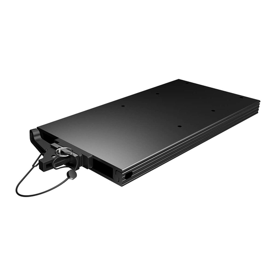
MKA-51 ELECTRIC-STEER
QUICK RELEASE BRACKET
C
C
38
38
22
22
B B
2 2
6 6
A A
• 7/16" Box End or
Open End Wrench
The mounting surface for the Bottom Plate must
NOTICE:
be completely flat. Rubber Washers can be used to shim
the Bottom Plate flat before hardware is tightened. The
Top Plate will not fit correctly unless the Bottom Plate is
installed completely flat.
1854051
18
18
20
20
24
24
28
28
36
36
30
30
34
34
40
40
32
32
12
12
16
16
4 4
8 8
10
10
• A second person to help
with the installation
©2022 Johnson Outdoors Marine Electronics, Inc.
26
26
14
14
Advertisement

Related Manuals for MINN KOTA MKA-51


Summary of Contents for MINN KOTA MKA-51
- Page 1 MKA-51 ELECTRIC-STEER QUICK RELEASE BRACKET 1854051 Compatible with Minn Kota® Freshwater Electric-Steer Trolling Motor models, including the Ulterra™, Terrova®, PowerDrive™, PowerDrive V2 and DeckHand 40. Item / Part # Description Qty. Assembly A (Items 2-10) 2994936 BAG ASM, ES SLIDING QRB 2223446 SCREW-1/4-20 X 2"...
- Page 2 The MKA-51 Quick Release Bracket is designed to work on a number of Minn Kota trolling motors. The base extrusion or mounting bracket of the trolling motors may vary. Please note the appearance of the applicable trolling motors and mounting bracket. For a complete list of motors compatible with the MKA-51, please refer to the website minnkotamotors.com.
-
Page 3: Installation
“off.” Place the mount on an elevated, level surface such as a workbench or the tailgate of a pickup. The motor should be in the stowed position. A motor may weigh up to 65lbs. Minn Kota NOTICE: Stowed Stowed... - Page 4 Remove the four Sideplate screws using a #3 Phillips Screwdriver. Two Screws will be located on each side of the mount. Remove the Right Sideplate. Swing the Left Sideplate out and away from the Base Extrusion. Removing the sideplates exposes the mounting holes in the Base Extrusion.
- Page 5 ITEM(S) NEEDED #C x 1 #4 x 6 #10 x 6 #6 x 6 Place the flat side of the Top Plate (Assembly #C) Nylock Nuts Nylock Nuts against the bottom of the Base Extrusion. Align the Outboard Outboard Mounting Holes in the Top Plate with the Mounting Flat Washer Flat Washer Holes in the Base Extrusion that were exposed when...
- Page 6 Installing the Top Plate to a DeckHand 40 ITEM(S) NEEDED #4 x 4 #10 x 4 #6 x 4 #C x 1 For more detailed instructions on installing a Outboard Outboard NOTICE: Davit Davit Base Base DeckHand 40, refer to the DeckHand 40 owner's manual online at minnkotamotors.com.
- Page 7 Power Cables Make sure that the Power Cables from the battery are disconnected or that the breaker, if equipped, is “off.” A motor may weigh up to 65lbs. Minn Kota NOTICE: recommends having a second person help with the installation.
- Page 8 ITEM(S) NEEDED #4 x 6 #10 x 6 #6 x 6 #C x 1 This installation will require six Clipped NOTICE: Power Tilt Power Tilt Washers (Part #2201725) from the Ulterra Bag Assembly (Part #2994917). To prevent seizing of the stainless steel NOTICE: hardware, do not use high-speed installation tools.
- Page 9 CAUTION Use extra care to avoid pinching and damaging the sensor wires that run alongside the Base Extrusion when installing and tightening the mounting hardware. Move to the other side of the Ulterra to install the Mounting Holes Mounting Holes remaining hardware.
- Page 10 Quick Release Bracket. The exact placement of the motor when mounting may vary depending on the boat, boat deck, and base extrusion or bracket the MKA-51 is being mounted to. The Ulterra motor cannot be deployed before mounting and connecting a power source.
- Page 11 With an Awl or similar marking tool, mark the side and Bottom Bottom rear edges of the Bottom Plate on the bow of the boat. Plate Plate Bow of Bow of Bow of Bow of Boat Boat Remove the Pin and open the Cam Lever. Separate Boat Boat the Top Plate and motor from the Bottom Plate.
-
Page 12: Completing The Installation
Improper alignment will allow the motor to fall off, even if the Cam Lever is locked. Transporting Transporting For warranty information, please visit minnkotamotors.com. Minn Kota Consumer & Technical Service 121 Power Drive Johnson Outdoors Marine Electronics, Inc. Mankato, MN 56001 PO Box 8129 Phone (800) 227-6433 ©2022 Johnson Outdoors Marine Electronics, Inc. - Page 13 SUPPORT À DÉGAGEMENT RAPIDE À COMMANDE ÉLECTRIQUE MKA-51 1854051 Compatible avec les modèles de moteur de pêche à la traîne en eau douce à commande électrique Minn Kota®, y compris Ulterra™, Terrova®, PowerDrive™, PowerDrive V2 et DeckHand 40. Article/ Nº de Description Qté...
- Page 14 écart latéral entre les plaques. Le support à dégagement rapide MKA-51 est conçu pour fonctionner sur plusieurs moteurs de pêche à la traîne Minn Kota. L’extrusion de la base ou le support de montage des moteurs de pêche à...
- Page 15 Les deux trous les plus proches en-bord ne sont pas utilisés pour installer le support. INSTALLATION Ouverture du support ARTICLE(S) REQUIS #C x 1 #B x 1 Prenez le support à dégagement rapide MKA-51, qui Plaque Plaque comprend la plaque supérieure (assemblage nº C) et supérieure supérieure Glisser 1½...
- Page 16 Déployé Déployé Un moteur peut peser jusqu’à 65 lb (29,5 kg). AVIS : Minn Kota recommande d’obtenir l’aide d’une deuxième personne pour l’installation. Retirez les quatre vis de la plaque latérale en utilisant un tournevis cruciforme nº 3. Deux vis seront situées de chaque côté...
- Page 17 ARTICLE(S) REQUIS #C x 1 #4 x 6 #10 x 6 #6 x 6 Placez le côté plat de la plaque supérieure Écrou Nylock Écrou Nylock (ensemble nº C) contre le bas de l’extrusion de la Hors-bord Hors-bord base. Enlignez les trous de montage dans la plaque Rondelle plate Rondelle plate supérieure et les trous de montage dans l’extrusion...
- Page 18 Installation de la plaque supérieure sur un DeckHand 40 ARTICLE(S) REQUIS #4 x 4 #10 x 4 #6 x 4 #C x 1 Pour obtenir des instructions plus détaillées Hors-bord Hors-bord AVIS : Bossoir Bossoir Base Base sur l’installation d’un DeckHand 40, consultez le manuel du propriétaire du DeckHand 40 en ligne sur minnkotamotors.com.
- Page 19 échéant, est en position « arrêt ». Un moteur peut peser jusqu’à 65 lb (29,5 kg). AVIS : Minn Kota recommande d’obtenir l’aide d’une deuxième personne pour l’installation. Arrimé Arrimé Déployé...
- Page 20 ARTICLE(S) REQUIS #4 x 6 #10 x 6 #6 x 6 #C x 1 Mécanisme Mécanisme Pour prévenir le grippage de la quincaillerie AVIS : d’inclinaison motorisé d’inclinaison motorisé en acier inoxydable, n’utilisez pas d’outils haute vitesse pour l’installation. Mouiller les vis ou appliquer un produit antigrippant peut aider à...
- Page 21 ATTENTION Use extra care to avoid pinching and damaging the sensor wires that run alongside the Base Extrusion when installing and tightening the mounting hardware. Passez de l’autre côté du moteur Ulterra pour installer Trous de montage Trous de montage le reste du matériel.
- Page 22 MKA-51 est monté. Le moteur Ulterra ne peut pas être déployé avant le montage et la connexion à une source d’alimentation.
- Page 23 Avec un poinçon ou un outil de marquage similaire, Plaque Plaque marquez les bords latéraux et arrière de la plaque de fond inférieure inférieure Proue du Proue du Proue du Proue du sur l’étrave du bateau. bateau bateau bateau bateau Retirez la goupille et ouvrez le levier à...
-
Page 24: Terminer L'installation
à came est verrouillé. En transport En transport Pour obtenir des renseignements sur la garantie, veuillez visiter minnkotamotors.com. Minn Kota Consumer & Technical Service 121 Power Drive Johnson Outdoors Marine Electronics, Inc. Mankato, MN 56001...
Need help?
Do you have a question about the MKA-51 and is the answer not in the manual?
Questions and answers