
Related Manuals for Endress+Hauser HMX50


Summary of Contents for Endress+Hauser HMX50
- Page 1 Products Solutions Services BA00371F/00/EN/14.17 71372397 Operating Instructions HART Loop Converter HMX50 Signal Transmitter...
-
Page 2: Table Of Contents
HART Loop Converter HMX50 Index Safety instructions ..........................4 Symbols used ............................4 Target Group/Personnel ........................5 Reference to further documentation ....................5 Intended Use ............................6 Improper Use ............................6 Mounting/Installation .........................6 Operation, Maintenance, Repair ......................7 Delivery, Transport, Disposal ......................7 Product Specifications ..........................8... - Page 3 HART Loop Converter HMX50 Unit ..............................23 HARTcom ............................24 Current Outputs ..........................28 Relay Contact Outputs ........................32 Service ..............................40 Operation ............................41 Indicators during Operation ......................41 Fault Message ............................44 Technical Specifications ........................44 Default Settings ..........................44 Further technical data ........................47 Endress+Hauser...
-
Page 4: Safety Instructions
HART Loop Converter HMX50 Safety instructions 1.1 Symbols used Symbol Meaning DANGER! DANGER This symbol alerts you to a dangerous situation. Failure to avoid this situation will result in serious or fatal injury. WARNING! WARNING This symbol alerts you to a dangerous situation. Failure to avoid this situation can result in serious or fatal injury. -
Page 5: Target Group/Personnel
HART Loop Converter HMX50 1.2 Target Group/Personnel The plant owner is responsible for its planning, installation, commissioning, operation, maintenance and disassembly. Mounting, installation, commissioning, operation, maintenance and disassembly of any devices may only be carried out by trained, qualified personnel. The instruction manual must be read and understood. -
Page 6: Intended Use
HART Loop Converter HMX50 1.4 Intended Use The devices are only approved for appropriate and intended use. The device must only be operated in the ambient temperature range and at the relative humidity (non-condensing) specified. The devices are used in C&I technology for the galvanic isolation of C&I signals such as 20 mA and 10 V standard signals or alternatively for adapting or standardizing signals. -
Page 7: Operation, Maintenance, Repair
HART Loop Converter HMX50 hazardous areas, whereby special attention must be paid to maintain separation distances to all non-intrinsically safe circuits according to the requirements in IEC/EN 60079-14. All separation distances between two adjacent intrinsically safe circuits need to be observed in accordance with IEC/EN 60079-14. -
Page 8: Product Specifications
HART Loop Converter HMX50 compliance with the applicable laws and guidelines of the respective country. Product Specifications 2.1 Function The HART Loop Converter is an isolated barrier suitable for intrinsically safe applications. The device supplies field devices and can be connected in parallel to existing HART circuits. -
Page 9: Assembly
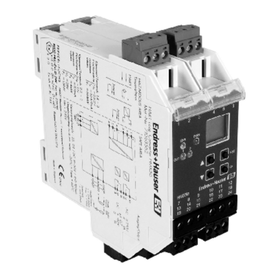
HART Loop Converter HMX50 2.2 Assembly The following are located on the front of the HMX50: • a display for showing the measured values, the current output values and fault messages and for displaying in parameterization mode • four keys for selecting the displayed... -
Page 10: Dimensions
HART Loop Converter HMX50 2.3 Dimensions 40 (1.57) 115 (4.53) A0034621 Number of terminal blocks max. 10 • Dimension drawing with screw terminals • When using screw terminals with test sockets the device is 124 mm (4.9 in) in height. -
Page 11: Mounting
HART Loop Converter HMX50 3.2 Mounting Snap the device onto the DIN mounting rail in a vertical downward movement. A0034620 CORRECT: Device snapped on vertically. INCORRECT: Device snapped on from the side. Can damage the contacts and cause the device to fail. -
Page 12: Connection
HART Loop Converter HMX50 3.3 Connection The removable terminal blocks simplify connection and control cabinet construction significantly. These terminal blocks offer adequate space for the connection of leads with core cross-sections of up to 2.5 mm² (14 AWG). The terminal blocks are coded with red coding pins so misconnection of terminal blocks are eliminated. -
Page 13: Output Connection (Drive Circuit)
HART Loop Converter HMX50 3 - 4 3 - 5 HART-Loop A0034628 3.3.2 Output Connection (drive circuit) Connecting the Drive Circuit 1. Connect the drive circuit to the green terminals. 2. Note the tightening torque of the terminal screws. The tightening torque is 0.5 Nm ... - Page 14 HART Loop Converter HMX50 The following connections are available: • Terminals 10 ... 12: output I (relay 1 (change-over contact)) • Terminals 16 ... 18: output II (relay 2 (change-over contact)) • Terminals 7 ... 9: output III, current output as source (7/8) or sink (7/9) •...
-
Page 15: Connecting A Hart Handheld To The Field Device
HART Loop Converter HMX50 3.3.3 Connecting a HART Handheld to the Field Device DANGER Risk of explosion Danger of explosion when using a noncertified HART handheld in a hazardous area. ‣ Use a HART handheld certified for use in hazardous areas if the field cables lead into a hazardous area. - Page 16 HART Loop Converter HMX50 Polling Mode (command and answer) The isolated barrier deactivates the burst configuration of the field device. The isolated barrier performs the field device query using HART command 3. See chapter 3.4.6. Procedure to Restore Burst Mode...
-
Page 17: Configuration
HART Loop Converter HMX50 3.4 Configuration CAUTION Fault in the plant Changing the device data changes the device function. ‣ Before entering new device data, make sure the plant is not endangered by changing the device data. Configuring the Device ▴... -
Page 18: Parameterization Mode
HART Loop Converter HMX50 Error current The menu items from the lowest menu level are outlined in bold. 3.4.1 Parameterization Mode After being switched on, the device is in display mode. If you have password protection enabled, you must enter the password every time you transition from display mode to parameterization mode. -
Page 19: Password Protection
HART Loop Converter HMX50 Calling up Parameterization Mode Press the OK and ESC buttons simultaneously for approx. 1 second. The device changes from display mode to parameterization mode. Exiting Parameterization Mode 1. Press the ESC once or multiple times. The number of times depends on which menu level you are in. -
Page 20: Entering Numbers
HART Loop Converter HMX50 Canceling Password Entry You can cancel password entry at any time. Press the ESC button. The device switches to display mode. 3.4.3 Entering Numbers At the lowest menu level of the Parameter menu, you have the option of selecting or entering a numerical value. -
Page 21: Entering Floating Point Figures
HART Loop Converter HMX50 5. The new value does not flash. The value is stored. Entering a Numerical Value 1. Select the parameter where you want to enter the numerical value. 2. Press the OK button. The current value flashes. - Page 22 HART Loop Converter HMX50 0.012 34 12.34 E-03 - 0.012 3 -12.3 E-03 0.001 234 1.234 E-03 - 0.001 23 -1.23 E-03 0.000 123 4 123.4 E-06 - 0.000 123 -123 E-06 For a floating point figure, you must enter the following parameters: •...
- Page 23 HART Loop Converter HMX50 11. Confirm your entry with OK. The new value is stored. 3.4.5 Unit At the lowest menu level of the Unit menu, you have the option of selecting the unit type for the HART variables. • auto The device displays the unit which is transferred from connected HART field devices for the HART variables PV, SV, TV, QV.
- Page 24 HART Loop Converter HMX50 Changing the Custom Tag of HART Variables 1. Select the HART variable for which you would like to change the custom tag. 2. Press the OK button. 3. Select the Custom Tag menu. The device displays: ...
- Page 25 HART Loop Converter HMX50 HARTcom —— Mode —— secondary ▾ ▴ ▾ ▴ primary TimeOut —— 5 s ... 60 s ▾ ▴ ComControl —— auto detect ▾ ▴ ▾ ▴ polling ▾ ▴ burst ShortAddress —— 0 ... 15 ▾...
- Page 26 HART Loop Converter HMX50 Selecting a Mode The device functions as primary or secondary HART master according to the HART standard. The device is compatible with each HART handheld and for every other HART master. ▴ ▾ 1. Use the buttons to select whether the device should operate as a primary or secondary HART master.
- Page 27 HART Loop Converter HMX50 5. Confirm your entry with OK. NOTICE Note that the field device can be put into burst mode, in accordance to the isolated barrier configuration. This also applies when a different HART master is in the HART circuit. If a different HART master changes the burst configuration of the field device, the isolated barrier waits until the other HART master logs out of the HART circuit.
- Page 28 HART Loop Converter HMX50 Activating Rebuild If the connection to the field device has been lost, the localization phase can be performed with Rebuild without switching the device off and on again. ▴ ▾ 1. Select On Rebuild with the buttons.
- Page 29 HART Loop Converter HMX50 Characteristic —— 4 - 20 unlimited ▾ ▴ ▾ ▴ 4 - 20 NE 43 Start value —— (s. page 30) ▾ ▴ End value —— (s. page 31) ▾ ▴ Error current —— down ▾...
- Page 30 HART Loop Converter HMX50 Selecting an Assignment The values of the selected HART variable (PV, SV, TV, QV) are shown on the current output. The number of available variables depends on the HART field device. When selecting disabled, the downscale fault current of 0 mA or 2 mA is constantly present at the current output, depending on the characteristic.
- Page 31 HART Loop Converter HMX50 Define the End Value Make sure during configuration that the end value is at least 1 % greater than the start value. 1. Enter the end value as a floating point figure. For entering floating point figures, see chapter 3.4.4.
- Page 32 HART Loop Converter HMX50 3. Select the fault current up. The fault message is indicated by a high current value. 4. Select the fault current hold. The last measured value before the fault occurred is stored. 5. Confirm your entry with OK.
- Page 33 HART Loop Converter HMX50 Selecting Relay Contact Output Menus ▴ ▾ 1. Select the desired relay contact output using the buttons. 2. Confirm your entry with OK. The relay contact output menus trip value and fault signal are displayed. The active menu is marked as On.
- Page 34 HART Loop Converter HMX50 ▾ ▴ Min/Max —— ▾ ▴ Trip point —— (s. page 37) ▾ ▴ Hysteresis —— (s. page 37) ▾ ▴ Switching mode —— Passive ▾ ▴ ▾ ▴ Active ▾ ▴ Restart inhibit —— ▾...
- Page 35 HART Loop Converter HMX50 Selecting an Assignment The values of the HART variables selected here (PV, SV, TV, QV) are monitored using a relay contact output. The number of available variables depends on the HART field device. When disabled is selected, the relay remains constant in a de-energized state.
- Page 36 HART Loop Converter HMX50 A0034630 Max. trip point Max - hysteresis Min + hysteresis Min trip point Switching direction MAX, switching mode Active Switching direction MAX, switching mode Passiv Switching direction MIN, switching mode Active Switching direction MIN, switching mode Passiv...
- Page 37 HART Loop Converter HMX50 Defining the Trip Point 1. Enter the starting point as a floating point figure. For entering floating point figures, see chapter 3.4.4. The defined unit from the Unit menu is used as the unit. See chapter 3.4.5.
- Page 38 HART Loop Converter HMX50 • When the value of the trip point is out of range (exceeded or not reached) for a period of time longer than the delay time, the relay switches. • When the value of the trip point ± hysteresis is in range (not reached or exceeded) for a period of time longer than the delay time, the relay switches back.
- Page 39 HART Loop Converter HMX50 Calling up a Fault Message ▴ ▾ 1. Use the buttons to select the Fault message menu. 2. If the fault message menu is activated, press the OK button once. The Restart inhibit submenu is displayed.
- Page 40 HART Loop Converter HMX50 3.4.9 Service In the Service menu, you have the option of specifying basic device parameters. Service —— Language —— ENG (English) ▾ ▴ ▾ ▴ DE (German) Password —— On password ▾ ▴ ▾ ▴ OFF password ▾...
- Page 41 HART Loop Converter HMX50 Activating Password Protection To protect parameterization from unauthorized changes, you can enable password protection. Information about password protection see chapter 3.4.2. ▴ ▾ 1. Use the buttons to select the desired setting. 2. To enable password protection, select On Password.
- Page 42 HART Loop Converter HMX50 LED-Anzeigen Status Description No power supply Green LED Flashes regularly Start-up phase, self-test Normal function Displays a single HART fault message received by the Flashes briefly field device Invalid HART data (missing communication or fault in...
- Page 43 HART Loop Converter HMX50 • LOOP Poll The isolated barrier performs the field device query using the HART command 3. • LOOP Burst The isolated barrier receives the HART command 3 of the field device. • LOOP Mixed The isolated barrier performs the field device query using the HART command 3 (polling).
- Page 44 HART Loop Converter HMX50 4.2 Fault Message The following table shows which fault message the current outputs send to the controller, based on the characteristic. 4 - 20 unlimited 4 - 20 NE43 Setting 0 mA down Cannot be distinguished from falling 2.0 mA...
- Page 45 HART Loop Converter HMX50 Menu Parameters Default setting Custom value PV Type auto SV Type auto Unit TV Type auto QV Type auto Mode secondary TimeOut 10 s HARTcom ComControl auto detect ShortAddress LocateMethod search Assignment disabled Characteristic 4 - 20 NE 43 →...
- Page 46 HART Loop Converter HMX50 Menu Parameters Default setting Custom value Assignment disabled Characteristic 4 - 20 NE 43 → Start value 0.000 Output Iout3 End value 100.0 Fault current down Trip value On (selected) → disabled Trip value Assignment →...
- Page 47 HART Loop Converter HMX50 Menu Parameters Default setting Custom value Trip value On (selected) → disabled Trip value Assignment → Trip value Min/Max → 80.00 Trip value Trip point → → Output Rel2 Trip value Hysteresis 10.00 → Trip value...
- Page 48 71372397 www.addresses.endress.com...
Need help?
Do you have a question about the HMX50 and is the answer not in the manual?
Questions and answers