Table of Contents
Advertisement
Advertisement
Table of Contents

Related Manuals for MSI MS-6567


Summary of Contents for MSI MS-6567
- Page 1 Version 1.1...
- Page 2 Shielded interface cables and A.C. power cord, if any, must be used in order to comply with the emission limits. VOIR LA NOTICE D’INSTALLATION AVANT DE RACCORDER AU RESEAU. Micro-Star International MS-6567 Tested to comply with FCC Standard For Home or Office Use...
-
Page 3: Copyright Notice
Edition Jun. 2002 Copyright Notice The material in this document is the intellectual property of MICRO-STAR INTERNATIONAL. We take every care in the preparation of this document, but no guarantee is given as to the correctness of its contents. Our products are under continual improvement and we reserve the right to make changes without notice. -
Page 4: Safety Instructions
Safety Instructions Always read the safety instructions carefully. Keep this User’s Manual for future reference. Keep this equipment away from humidity. Lay this equipment on a reliable flat surface before setting it up. The openings on the enclosure are for air convection hence protects the equipment from overheating. -
Page 5: Table Of Contents
Live BIOS™/Live Driver™ ... 1-7 Live Monitor™ ... 1-8 D-Bracket™ (Optional) ... 1-9 S-Bracket (Optional) ... 1-11 MSI DVD (5.1 Channel) ... 1-12 Chapter 2. Hardware Setup ... 2-1 Central Processing Unit: CPU ... 2-2 CPU Installation Procedures ... 2-2 Installing the CPU Fan ... - Page 6 Parallel Port Connector: LPT1 ... 2-11 Joystick/Midi Connector ... 2-12 Audio Port Connectors ... 2-12 Connectors ... 2-13 Floppy Disk Drive Connector: FDD1 ... 2-13 Hard Disk Connectors: IDE1 & IDE2 ... 2-14 Fan Power Connectors: CPUFA/SYSFA ... 2-15 IrDA Infrared Module Header: JIR1 ... 2-16 Bluetooth Connector: JBT1 (Optional) ...
- Page 7 Advanced Chipset Features ... 3-12 Power Management Features ... 3-14 PNP/PCI Configurations ... 3-18 Integrated Peripherals ... 3-21 PC Health Status ... 3-25 Frequency/Voltage Control ... 3-26 Set Supervisor/User Password ... 3-28 Load High Performance/BIOS Setup Defaults ... 3-29 Appendix A: Using 4- or 6-Channel Audio Function ... A-1 Installing the Audio Driver ...
-
Page 8: Chapter 1. Getting Started
Chapter 1. Getting Started Getting Started Thank you for purchasing 645E Max2 (MS-6567) series ATX motherboard. The 645E Max2 (MS-6567) series is a superior computer mainboard based on SiS 645DX & 962L chipsets for optimal system efficiency. Designed to fit the advanced Intel 478 pin package, the motherboard provides a high performance and profes- sional desktop platform solution. -
Page 9: Mainboard Specification
Chapter 1 Mainboard Specification Supports Socket 478 for P4 processors (Willimate 478 and Northwood 478) FSB @ 400/533 MHz (100/133 MHz QDR) Supports 1.3GHz, 1.4GHz, ... 2.4GHz and up Chipset SiS 645DX chipset (702 BGA) - Supports 64-bit P4 processors at 533MHz - Supports 32-bit AGP 4x/2x slot - Supports 64-bit high performance DDR333 / DDR266 memory controller - Supports bi-directional 16-bit data bus with 533MHz bandwidth MuTIOL... - Page 10 Internal: - Front Panel (2 x 5) w/ Intel pin definition - Front USB (2 x 5) w/ Intel pin definition - Front Audio (2 x 5) w/ Intel pin definition - Front IR (2 x 5) w/ Intel pin definition - IDE x 2, Floppy, ATX power connector - CPU Fan, System Fan, Audio (CD-in) Audio...
-
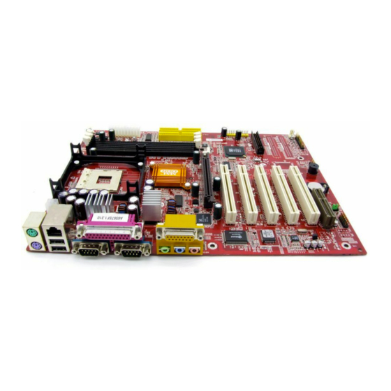
Page 11: Mainboard Layout
JCD1 8101L (Optional) Winbond W83697HF BIOS Codec (ALC201A/ALC650) JMOD1 (Optional) JBAT1 JSP3 645E Max2 (MS-6567) series ATX Mainboard CPUFA 645DX AGP Slot PCI Slot 1 PCI Slot 2 PCI Slot 3 PCI Slot 4 PCI Slot 5 BATT JBT1 (Optional) -
Page 12: Quick Components Guide
Quick Components Guide Component Function DDR1~3 Installing DDR SDRAM modules Socket 478 Installing CPU CPUFA Connecting to CPUFAN SYSFA Connecting to SYSTEM FAN ATX Power Supply Installing power supply JPW1 Connecting to 12V power connector IDE1 & IDE2 Connecting to IDE hard disk drive IDE3 &... -
Page 13: Fuzzy Logic™ Iii
Chapter 1 MSI Special Features Fuzzy Logic™ III The Fuzzy Logic™ III utility allows users to overclock the CPU FSB (Front Side Bus) frequency in the Windows environment. Select the CPU frequency you prefer and click Go to apply the frequency or click Save allow- ing the system to run at the specified frequency each time when the system is powered on. -
Page 14: Live Bios™/Live Driver
Web site. To use the function, you need to install the “MSI Live Update Series 2” application. After the installation, the “MSI Live Update Series 2” icon (as shown on the right) will appear on the screen. Double click the “MSI Live Update Series 2” icon, and the following screen will appear: Five buttons are placed on the leftmost pane of the screen. -
Page 15: Live Monitor
Live Monitor™ The Live Monitor™ is a tool used to schedule the search for the latest BIOS/drivers version on the MSI Web site. To use the function, you need to install the “MSI Live Update Series 2” application. After the installation, the “MSI Live Monitor” icon (as shown on the right) will appear on the screen. -
Page 16: D-Bracket™ (Optional)
D-Bracket™ (Optional) D-Bracket™ is a USB bracket integrating four Diagnostic LEDs, which use graphic signal display to help users understand their system. The LEDs provide up to 16 combinations of signals to debug the system. The 4 LEDs can debug all problems that fail the system, such as VGA, RAM or other failures. This special feature is very useful for the overclocking users. - Page 17 Chapter 1 D-Bracket Processor Initialization - This will show information regarding the processor (like brand name, system bus, etc…) Testing RTC (Real Time Clock) Initializing Video Interface - This will start detecting CPU clock, checking type of video onboard. Then, detect and initialize the video adapter. BIOS Sign On - This will start showing information about logo, processor brand name, etc….
-
Page 18: S-Bracket (Optional)
S-Bracket (Optional) S-Bracket is a bracket which provides 2 SPDIF jacks for digital audio transmission and 2 analog Line-Out connectors for additional 4-channel ana- log audio output. With the S-Bracket, your system will be able to perform 6- channel audio operation for wonderful surround sound effect, or connect to Sony &... -
Page 19: Msi Dvd (5.1 Channel)
Dolby Digital format first. To play DVD with 6-channel audio output, you must configure both the MSI DVD application and the audio codec’s software utility. Otherwise, the 6- channel audio function will not work properly. For information on how to select 6-channel mode in the audio software utility, refer to Appendix. - Page 20 Getting Started 4. Click OK. For more information about MSI DVD, you can refer to the online help coming with the application. To enter the online help: 1. Click on the icon at the bottom-right corner of the control panel.
-
Page 21: Chapter 2. Hardware Setup
Chapter 2. Hardware Setup Hardware Setup This chapter provides you with the information about hardware setup procedures. While doing the installation, be careful in holding the compo- nents and follow the installation procedures. For some components, if you install in the wrong orientation, the components will not work properly. Use a grounded wrist strap before handling computer components. -
Page 22: Central Processing Unit: Cpu
Chapter 2 Central Processing Unit: CPU The mainboard supports Intel package. The mainboard uses a CPU socket called PGA478 for easy CPU installation. When you are installing the CPU, make sure the CPU has a heat sink and a cooling fan attached on the top to prevent overheating. If you do not find the heat sink and cooling fan, contact your dealer to purchase and install them before turning on the computer. -
Page 23: Installing The Cpu Fan
CPU cooling fan and heatsink on top of the CPU. Follow the instructions below to install the Heatsink/Fan: Locate the CPU and its retention mechanism on the motherboard. retention mechanism Mount the fan on top of the heatsink. -
Page 24: Cpu Core Speed Derivation Procedure
CPU Clock Core/Bus ratio then CPU core speed Overclocking This motherboard is designed to support overclocking. WARNING! However, please make sure your components are able to tolerate such abnormal setting, while doing overclocking. Any attempt to operate beyond product specifications is not recommended. -
Page 25: Memory
Memory The mainboard provides 3 sockets for 184-pin DDR SDRAM DIMM (Double In-Line Memory Module) modules and supports the memory size up to 3GB. You can install PC2700/DDR333, PC2100/DDR266 or PC1600/DDR200 DRAM modules on the DDR DIMM slots (DIMM 1~3). Introduction to DDR SDRAM DDR (Double Data Rate) SDRAM is similar to conventional SDRAM, but doubles the rate by transferring data twice per cycle. -
Page 26: Dimm Module Combination
Chapter 2 DIMM Module Combination Install at least one DIMM module on the slots. Memory modules can be installed on the slots in any order. You can install either single- or double- sided modules to meet your own needs. Memory modules can be installed in any combination as follows: Slot DIMM 1 (Bank 0 &... -
Page 27: Power Supply
Power Supply The mainboard supports ATX power supply for the power system. Be- fore inserting the power supply connector, always make sure that all compo- nents are installed properly to ensure that no damage will be caused. ATX 20-Pin Power Connector: CONN1 This connector allows you to connect to an ATX power supply. -
Page 28: Back Panel
Chapter 2 Back Panel The Back Panel provides the following connectors: (Optional) Mouse Keyboard USB Mouse Connector The mainboard provides a standard PS/2 ® attaching a PS/2 mouse. You can plug a PS/2 connector. The connector location and pin assignments are as follows: PS/2 Mouse (6-pin Female) Parallel COM A... -
Page 29: Keyboard Connector
Keyboard Connector The mainboard provides a standard PS/2 ® for attaching a PS/2 keyboard. You can plug a PS/2 this connector. PS/2 Keyboard (6-pin Female) USB Connectors The mainboard provides a OHCI (Open Host Controller Interface) Uni- versal Serial Bus root for attaching USB devices such as keyboard, mouse or other USB-compatible devices. -
Page 30: Serial Port Connectors: Com A & Com B
Chapter 2 Serial Port Connectors: COM A & COM B The mainboard offers two 9-pin male DIN connectors as serial port COM A & COM B. The ports are 16550A high speed communication ports that send/receive 16 bytes FIFOs. You can attach a serial mouse or other serial devices directly to the connectors. -
Page 31: Parallel Port Connector: Lpt1
Parallel Port Connector: LPT1 The mainboard provides a 25-pin female centronic connector as LPT. A parallel port is a standard printer port that supports Enhanced Parallel Port (EPP) and Extended Capabilities Parallel Port (ECP) mode. Pin Definition SIGNAL DESCRIPTION STROBE Strobe DATA0 Data0... -
Page 32: Joystick/Midi Connector
Chapter 2 Joystick/Midi Connector You can connect a joystick or game pad to this connector. Audio Port Connectors Line Out is a connector for Speakers or Headphones. Line In is used for external CD player, Tape player, or other audio devices. Mic is a connector for microphones. -
Page 33: Connectors
Connectors The mainboard provides connectors to connect to FDD, IDE HDD, case, modem, USB Ports, IR module, bluetooth module, SPDIF bracket and CPU/ System FAN. Floppy Disk Drive Connector: FDD1 The mainboard provides a standard floppy disk drive connector that supports 360K, 720K, 1.2M, 1.44M and 2.88M floppy disk types. -
Page 34: Hard Disk Connectors: Ide1 & Ide2
Chapter 2 Hard Disk Connectors: IDE1 & IDE2 The mainboard has a 32-bit Enhanced PCI IDE and Ultra DMA 33/66/100/ 133 controller that provides PIO mode 0~4, Bus Master, and Ultra DMA 33/66/ 100/133 function. You can connect up to four hard disk drives, CD-ROM, 120MB Floppy (reserved for future BIOS) and other devices. -
Page 35: Fan Power Connectors: Cpufa/Sysfa
Fan Power Connectors: CPUFA/SYSFA The CPUFA (processor fan) and SYSFA (system fan) support system cooling fan with +12V. It supports three-pin head connector. When connect- ing the wire to the connectors, always take note that the red wire is the positive and should be connected to the +12V, the black wire is Ground and should be connected to GND. -
Page 36: Irda Infrared Module Header: Jir1
Chapter 2 IrDA Infrared Module Header: JIR1 The connector allows you to connect to IrDA Infrared module. You must configure the setting through the BIOS setup to use the IR function. JIR1 is ® compliant with Intel Front Panel I/O Connectivity Design Guide. JIR1 Pin Definition Signal VCC5... -
Page 37: Front Panel Connectors: Jfp1 & Jfp2
Front Panel Connectors: JFP1 & JFP2 The mainboard provides two front panel connectors for electrical con- nection to the front panel switches and LEDs. JFP1 is compliant with Intel Front Panel I/O Connectivity Design Guide. SIGNAL HD_LED_P FP PWR/SLP HD_LED_N FP PWR/SLP RST_SW_N PWR_SW_P... -
Page 38: Modem Connector: Jmod1 (Optional)
Chapter 2 Modem Connector: JMOD1 (Optional) This connector is connected to an optional modem module. The modem module functions in the same way as a modem, which allows users to connect to the internet via the telephone line. JMOD1 Modem Module Connect to a telephone set SIGNAL BIT_CLK (to LAN controller) -
Page 39: Front Panel Audio Connector: Jaud1
Front Panel Audio Connector: JAUD1 The JAUD1 front panel audio connector allows you to connect to the front panel audio and is compliant with Intel Design Guide. SIGNAL AUD_MIC AUD_GND AUD_MIC_BIAS AUD_VCC AUD_FPOUT_R AUD_RET_R HP_ON AUD_FPOUT_L AUD_RET_L Note: If you don’t want to connect to the front audio header, pins 5 &... -
Page 40: Front Usb Connectors: Jusb1
Chapter 2 Front USB Connectors: JUSB1 Depending on the model you have purchased, your mainboard could provide ONE USB (Universal Serial Bus) pin header that allow you to connect optional USB ports for front panel. USB 1.1: The 645E Max2 series mainboard comes with one standard USB 2.0 pin header JUSB1 that is compliant to Intel USB 2.0 technology increases data transfer rate up to a maximum through- put of 480Mbps, which is 40 times faster than USB 1.1, and is ideal for... - Page 41 To Attach the Optional USB 2.0 Ports: 1. Take out the USB 2.0 bracket 2. Locate the JUSB3 and JUSB4 pin headers on the motherboard. 3. Connect the USB cables from USB 2.0 bracket to the JUSB3 and JUSB4 pin headers separately.
-
Page 42: Cd-In Connector: Jcd1
Chapter 2 CD-In Connector: JCD1 The connector is for CD-ROM audio connector. JCD1 2-22... -
Page 43: D-Bracket™ Connector: Jdb1
D-Bracket™ Connector: JDB1 The mainboard comes with a JDB1 connector for you to connect to D- Bracket™. D-Bracket™ is a USB Bracket integrating four LEDs and allows users to identify system problem through 16 various combinations of LED signals. For definitions of 16 signal combinations, please refer to D-Bracket™ (Optional) in Chapter 1. -
Page 44: S-Bracket Connector: Jsp3
Chapter 2 S-Bracket Connector: JSP3 The connector allows you to connect a S-Bracket for Sony & Philips Digital Interface (SPDIF). The S-Bracket offers 2 SPDIF jacks for digital audio transmission (one for optical fiber connection and the other for coaxial), and 2 analog Line-Out jacks for 4-channel audio output. -
Page 45: Jumpers
Jumpers The motherboard provides one jumper for you to set the computer’s function. This section will explain how to change your motherboard’s function through the use of the jumper. Clear CMOS Jumper: JBAT1 There is a CMOS RAM on board that has a power supply from external battery to keep the data of system configuration. -
Page 46: Slots
The CNR slot allows you to insert the CNR expansion cards. CNR is a specially designed network, audio, or modem riser card for ATX family motherboards. Its main processing is done through software and controlled by the motherboard’s chipset. The CNR slot of the mainboard supports audio and modem only. 2-26... -
Page 47: Pci Interrupt Request Routing
PCI Interrupt Request Routing The IRQ, abbreviation of interrupt request line and pronounced I-R-Q, are hardware lines over which devices can send interrupt signals to the microprocessor. The “AGP/PCI/USB/ACHIP” IRQ pins are typically connected to the PCI bus INT A# ~ INT D# pins as follows: PCI Slot 1 PCI Slot 2 PCI Slot 3... -
Page 48: Ami Bios Setup
Chapter 3. AMI ® BIOS Setup This chapter provides information on the AMI lows you to configure the system for optimum use. You may need to run the Setup program when: An error message appears on the screen during the system booting up, and requests you to run SETUP. -
Page 49: Entering Setup
Chapter 3 Entering Setup Power on the computer and the system will start POST (Power On Self Test) process. When the message below appears on the screen, press <DEL> key to enter Setup. DEL:Setup F11:Boot Menu If the message disappears before you respond and you still wish to enter Setup, restart the system by turning it OFF and On or pressing the RESET button. -
Page 50: Control Keys
Control Keys < > Move to the previous item < > Move to the next item Move to the item in the left hand < > < > Move to the item in the right hand <Enter> Select the item <Esc>... -
Page 51: The Main Menu
Chapter 3 The Main Menu Once you enter AMIBIOS NEW SETUP UTILITY, the Main Menu will appear on the screen. The Main Menu displays twelve configurable functions and two exit choices. Use arrow keys to move among the items and press <Enter> to enter the sub-menu. - Page 52 BIOS Setup ® PNP/PCI Configurations This entry appears if your system supports PnP/PCI. Integrated Peripherals Use this menu to specify your settings for integrated peripherals. PC Health Status Use this menu to show the current status of your PC, such as temperature, Vcore, and other settings.
-
Page 53: Standard Cmos Features
Chapter 3 Standard CMOS Features The items inside STANDARD CMOS SETUP menu are divided into 9 catego- ries. Each category includes none, one or more setup items. Use the arrow keys to highlight the item you want to modify and use the <PgUp> or <PgDn> keys to switch to the value you prefer. - Page 54 Pri Master/Pri Slave/Sec Master/Sec Slave Press PgUp/<+> or PgDn/<-> to select the hard disk drive type. The specifica- tion of hard disk drive will show up on the right hand according to your selection. Type Cylinders Heads Write Precompensation Sectors Maximum Capacity LBA Mode Block Mode...
-
Page 55: Advanced Bios Features
Chapter 3 Advanced BIOS Features Quick Boot Setting the item to Enabled allows the system to boot within 5 seconds since it will skip some check items. Available options: Enabled and Disabled. Full Screen Logo Show This item enables you to show the company logo on the bootup screen. Set- tings are: Silent BIOS... - Page 56 Boot Device Priority The items allow you to set the sequence of boot devices where AMIBIOS attempts to load the operating system. The settings are: Disabled IDE-0 IDE-1 IDE-2 IDE-3 Floppy ARMD-FDD ARMD-HDD CD/DVD Legacy SCSI Legacy Network The system will boot from the Network drive. BBS-0 BBS-1 BBS-2...
- Page 57 Chapter 3 Note: Available settings for “Boot Device Priority” vary depending on the bootable devices you have installed. For example, if you did not install a floppy drive, the setting “Floppy” does not show up. Try Other Boot Devices Setting the option to Yes allows the system to try to boot from other devices if the system fails to boot from the 1st/2nd/3rd boot device.
- Page 58 BIOS Setup ® Internal/External Cache Cache memory is additional memory that is much faster than conventional DRAM (system memory). When the CPU requests data, the system transfers the requested data from the main DRAM into cache memory, for even faster access by the CPU.
-
Page 59: Advanced Chipset Features
Chapter 3 Advanced Chipset Features Note: Change these settings only if you are familiar with the chipset. AGP Aperture Size The field selects the size of the Accelerated Graphics Port (AGP) aperture. Aperture is a portion of the PCI memory address range dedicated for graphics memory address space. - Page 60 BIOS Setup ® Timing Setting Mode The DRAM timing is controlled by the DRAM Timing Registers. The Timings programmed into this register are dependent on the system design. Slower rates may be required in certain system designs to support loose layouts or slower memory.
-
Page 61: Power Management Features
Chapter 3 Power Management Features Power Button Function This feature sets the function of the power button. Settings are: Power Off The power button functions as normal on/off button. Suspend When you press the power button, the computer enters the suspend/sleep mode, but if the button is pressed for more than four seconds, the computer is turned off. - Page 62 S1/POS The S1 sleep mode is a low power state. In this state, no system context is lost (CPU or chipset) and hardware maintains all system context. S3/STR The S3 sleep mode is a lower power state where the infor- mation of system cofiguration and open applications/ files is saved to main memory that remains powered while most other hardware components turn off to save energy.
- Page 63 Chapter 3 Set Wake Up Events Press <Enter> to enter the sub-menu and the following screen appears: Wake Up On Ring, Wake Up On PME#, Resume on PS/2 Mouse, PS/ 2 MOUSE Wake Select Mode, USB Wakeup From S3 These items specify whether the system will be awakened from power savingh modes when activity or input signal of the specified hardware peripheral or component is detected.
- Page 64 The item specify how the system will be awakened from power saving mode when input signal of the keyboard is detected. If set to Specific Key, <Ctrl+Alt+BackSpace> is the only one Power On event. If set to Password, please press <Enter> to input password and its maximum password is 5 character.
-
Page 65: Pnp/Pci Configurations
Chapter 3 PNP/PCI Configurations This section describes configuring the PCI bus system and PnP (Plug & Play) feature. PCI, or Peripheral Component Interconnect, is a system which allows I/O devices to operate at speeds nearing the speed the CPU itself uses when communicating with its special components. - Page 66 Allocate IRQ to PCI VGA Set to Yes allows BIOS to assign an IRQ to PCI/VGA card. Select No if you want to release the IRQ. PCI IDE BusMaster Set this option to Enabled to specify that the IDE controller on the PCI local bus has bus mastering capability.
- Page 67 Chapter 3 Set DMAs to PnP or ISA Press <Enter> to enter the sub-menu and the following screen appears: DMA Channel 0/1/3/5/6/7 These items specify the bus that the system DMA (Direct Memory Access) channel is used. The settings determine if AMIBIOS should remove a DMA from the available DMAs passed to devices that are configurable by the system BIOS.
-
Page 68: Integrated Peripherals
BIOS Setup ® Integrated Peripherals AC97 Audio Enabled allows the mainboard to detect whether an audio device is used. If the device is detected, the onboard AC’97 (Audio Codec’97) controller will be enabled; if not, it is disabled. Disable the controller if you want to use other controller cards to connect an audio device. - Page 69 Chapter 3 USB 2.0 Supports Set to Enabled if your need to use any USB 2.0 device in the operating system that does not support or have any USB 2.0 driver installed, such as DOS and SCO Unix. Setting options: Disabled, Enabled. USB KB/Mouse/FDD Legacy Support Set to Enabled if your need to use any USB KB/Mouse/FDD device in the operating system that does not support or have any USB driver installed.
- Page 70 BIOS Setup ® OnBoard Serial Port A/B These items specify the base I/O port addresses of the onboard Serial Port 1 (COM A)/Serial Port 2 (COM B). Selecting Auto allows AMIBIOS to automatically determine the correct base I/O port address. Settings: Auto, 3F8/COM1, 2F8/COM2, 3E8/COM3, 2E8/COM4 and Disabled.
- Page 71 Chapter 3 Parallel Port DMA Channel This feature needs to be configured only when Port Mode is set to the ECP mode. When Parallel Port is set to Auto, the field will show Auto indicating that BIOS automatically determines the DMA channel for the parallel port.
-
Page 72: Pc Health Status
PC Health Status This section shows the status of your CPU, fan, warning for overall system status. Vcore, +3.3V, +5.0V, +12V, -12V, -5.0V, Battery Voltage, SYSTEM Fan Speed, CPU FAN Speed, SYSTEM Temperature, CPU Temperature These items display the current status of all of the monitored hardware de- vices/components such as system voltages, temperatures and fan speeds. -
Page 73: Frequency/Voltage Control
Chapter 3 Frequency/Voltage Control This section describes how to set the Chassis Intrusion feature, CPU FSB frequency, monitor the current hardwae status including CPU/system temperatures, CPU/System Fan speeds, Vcore etc. Monitor function is available only if there is hardware monitoring mechanism onboard. Detect CPU FSB Clock This setting enables you to detect the CPU Front Side Bus clock frequency. - Page 74 CPU FSB Clock Setting Options 100MHz 101~132MHz 133~160MHz 161~200MHz DRAM Frequency This item shows the current frequency of DDR DRAM. (read only) CPU Multiple Factory This item allows users to select the CPU multiplier value. The default value of this item is Locked. Unused PCI Slot/DIMM Clk This setting enables you to stop or activate the unused PCI slot &...
-
Page 75: Set Supervisor/User Password
Chapter 3 Set Supervisor/User Password When you select this function, a message as below will appear on the screen: Type the password, up to six characters in length, and press <Enter>. The password typed now will replace any previously set password from CMOS memory. -
Page 76: Load Optimal/High Performance Defaults
Load Optimal/High Performance Defaults The two options on the main menu allow users to restore all of the BIOS settings to High Performance defaults or Optimal defaults. The High Perform- ance Defaults are the default values set by the mainboard manufacturer for the best system performance but probably will cause a stability issue. -
Page 77: Appendix A: Using 4- Or 6-Channel Audio Function
Appendix A: Using 4- or 6-Channel Audio Function The motherboard is equipped with Realtek ALC650 chip, which provides support for 6-channel audio output, including 2 Front, 2 Rear, 1 Center and 1 Subwoofer channel. ALC650 allows the board to attach 4 or 6 speakers for better surround sound effect. -
Page 78: Installing The Audio Driver
Appendix A Installing the Audio Driver You need to install the driver for Realtek ALC650 chip to function prop- erly before you can get access to 4-/6-channel audio operations. Follow the procedures described below to install the drivers for different operating systems. Installation for Windows 98SE/ME/2000/XP ®... -
Page 79: Using 4- Or 6-Channel Audio Function
Using 4- or 6-Channel Audio Function Click here Click Finish to restart the system. Select this option Click here... -
Page 80: Attaching Speakers
There are two ways to utilize the function and connect the speakers to your computer: Use the optional S-Bracket. If your motherboard supports S- Bracket and you have installed S-Bracket in the computer, you can connect two speakers to back panel’s Line-Out connector, and the rest of speakers to S-Bracket. - Page 81 2-Channel Analog Audio Output We recommend that you should still attach the speakers to BACK PANEL’s Line Out connector during 2-channel audio mode even though S- Bracket’s Line Out connectors function properly. Line Out (Front channels) Line In 4-Channel Analog Audio Output Line Out (Front channels) Line In Optical SPDIF jack...
- Page 82 Appendix A 6-Channel Analog Audio Output Line Out (Front channels) Line In Optical SPDIF jack Coaxial SPDIF jack Line Out (Center and Subwoofer channel) Line Out (Rear channels) Back Panel Digital Audio Output (2-Channel only) For digital audio output, use the SPDIF (Sony & Philips Digital Interface) connectors supplied by S-Bracket.
- Page 83 Optical SPDIF jack Coaxial SPDIF jack Line Out Line Out Plug Using BACK PANEL connectors only: The audio connectors on the back panel already provide 2-channel analog audio output function. The back panel’s audio connectors can be transformed to 4-/6-channel analog audio connectors automatically when you select correct setting in the software utility.
- Page 84 Appendix A 4-Channel Analog Audio Output Line Out (Front channels) Line Out (Rear channels) Description: Line In is converted to Line Out function under 4-channel configuration. 6-Channel Analog Audio Output Line Out (Front channels) Line Out (Rear channels) Line Out (Center and Subwoofer channel) Description: Both Line In and MIC are converted to Line Out function under 6-channel configuration.
-
Page 85: Selecting 4- Or 6-Channel Setting
Selecting 4- or 6-Channel Setting Click the audio icon screen. Select any surround sound effect you prefer from the “Environment” pull-down menu under the Sound Effect tab. Click the Speaker Configuration tab. Using 4- or 6-Channel Audio Function from the window tray at the bottom of the Click here and the pull- down menu will appear Click here... - Page 86 Click OK. Note: It is useless to select “Use S-Bracket” if your motherboard does not support or have the S-Bracket installed in the system. Make sure Use S-Bracket is NOT selected if you want to use audio connectors on the back panel only.
-
Page 87: Testing The Connected Speakers
Testing the Connected Speakers To ensure 4- or 6-channel audio operation works properly, you may need to test each connected speaker to make sure every speaker work properly. If any speaker fails to sound, then check whether the cable is inserted firmly to the connector or replace the bad speakers with good ones. -
Page 88: Playing Karaok
Appendix A Playing KaraOK The KaraOK function will automatically remove human voice (lyrics) and leave melody for you to sing the song. The function is applied only for 2- channel audio operation, so make sure “2 channels mode” is selected in the “No.
Need help?
Do you have a question about the MS-6567 and is the answer not in the manual?
Questions and answers